Tag: feed line

  • Common-Mode Current Explained: Why Ferrite Chokes Matter

    Common-Mode Current Explained: Why Ferrite Chokes Matter

    Common-mode current is one of those amateur-radio problems that can hide in plain sight. Your SWR may look reasonable, the radio may transmit normally, and yet the coax can still be carrying RF where you do not want it.
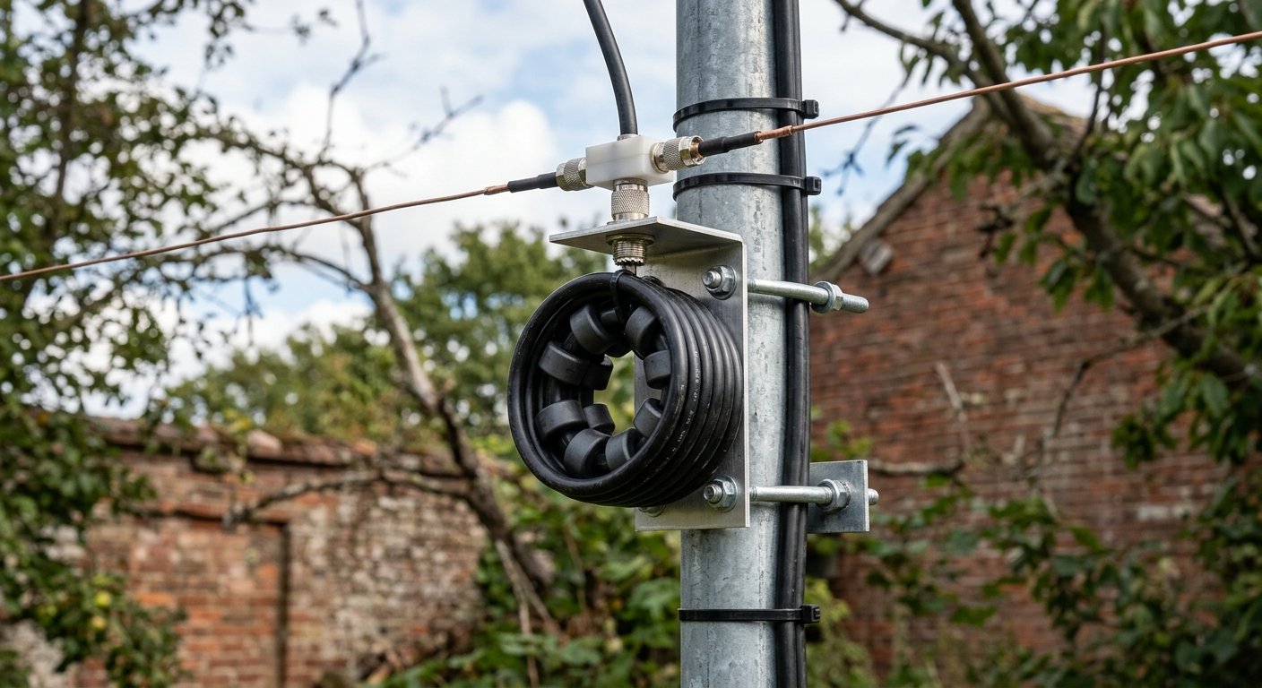
    Ferrite common-mode choke installed on an amateur radio coaxial feed line
    A ferrite common-mode choke on an HF coax feed line. Its job is to impede unwanted RF current on the outside of the shield.

    In a properly behaving coaxial feed line, the wanted RF currents flow on the center conductor and the inside surface of the shield. Those currents are equal and opposite, so fields outside the cable largely cancel. Common-mode current is different: it flows on the outside surface of the coax shield. Once that happens, part of the feed line can begin acting like another piece of the antenna.

    Why common-mode current matters

    If the outside of the coax becomes part of the radiating system, several things can happen. RF can travel back toward the operating position, antenna tuning can become less predictable, the radiation pattern can change, and nearby electronics may be more likely to experience interference. On receive, the same feed line can also pick up noise from devices in and around the house and carry it toward the antenna system.

    That does not mean every noise problem is caused by common-mode current, and a choke is not a universal cure. But when the outside of the feed line is carrying unwanted RF, a properly designed common-mode choke is one of the standard tools used to reduce it.

    What a ferrite choke actually does

    A common-mode choke adds impedance to RF current trying to flow along the outside of the coax shield. Ferrite material is especially useful because it can provide substantial impedance over a useful range of HF frequencies without interrupting the normal signal path inside the coax.

    The goal is not to “block the coax” or change its 50-ohm characteristic impedance. The wanted differential-mode signal still travels through the cable. The choke is aimed at the unwanted common-mode path on the outside of the shield.

    Ferrite type, the number of beads or turns, frequency, cable size, and power level all matter. This is why a random clip-on ferrite of unknown composition may work well at one frequency and do very little at another. ARRL guidance has long emphasized using ferrite material with known characteristics, while modern commercial HF feed-line chokes are commonly designed around materials such as Mix 31 for broad HF coverage.

    Where should the choke go?

    For antenna-system common-mode problems, the feed point is often the first place to consider. A choke there can help keep the outside of the coax from becoming part of the antenna. Depending on the installation, another choke near the station entrance can also be useful for reducing RF that might otherwise reach equipment in the shack.

    Placement is not one-size-fits-all. End-fed antennas, verticals, dipoles, and multiband systems can each create different current distributions. A choke can improve isolation, but it does not replace a sound antenna design, a suitable counterpoise or radial system where required, good bonding, and proper lightning protection.

    My station example

    At my own station I use purpose-built MyAntennas common-mode chokes, including a CMC-154S-3K at the coax entry. That is a different job from an antenna tuner. The tuner transforms impedance so the transmitter sees a suitable load; the common-mode choke is there to discourage unwanted RF current from traveling on the outside of the feed line.

    That distinction matters. A 1:1 SWR reading at the radio does not prove that common-mode current is absent, just as adding a choke does not automatically make a poorly designed antenna efficient.

    Signs that are worth investigating

    Common-mode current becomes especially worth checking when touching the radio, microphone, coax, or another cable changes the behavior of the station; when transmitted RF gets into audio, USB, computer, or control equipment; when antenna tuning changes as the feed line is moved; or when a feed line appears to be influencing the antenna pattern. Those symptoms can have other causes, but they are good reasons to examine feed-line isolation.

    The practical takeaway

    Think of a ferrite common-mode choke as an RF isolator for the outside of the feed line. It does not tune the antenna, and it does not replace good grounding, bonding, or antenna design. What it can do is keep the coax from participating in the antenna system in ways you did not intend.

    For many HF installations, that can mean more predictable tuning, less RF in the shack, and a cleaner boundary between the antenna and the station.

    Roger Quintana, NJ2RQ — LuffyHamVault.com

    Further reading

    For more technical background, see the ARRL Interference Primer and DX Engineering’s information on baluns, ununs and RF chokes.
  • What an Antenna Tuner Really Does — and What It Doesn’t Do

    What an Antenna Tuner Really Does — and What It Doesn’t Do

    If you have ever pressed TUNE, watched the SWR drop, and thought the antenna itself was suddenly “fixed,” you are not alone. An antenna tuner is one of the most useful pieces of HF gear in a station — but its name is a little misleading.

    The tuner does not usually change the physical antenna. Instead, it changes the impedance the radio sees so the transmitter can work into a load that is close to the 50 ohms most modern transceivers expect.

    What the tuner actually does

    An antenna system includes the antenna, feed line, connectors, and anything else between the transmitter and the radiating element. If that system does not present roughly 50 ohms at the radio, the transmitter sees a mismatch and the SWR rises.

    A tuner uses combinations of inductance and capacitance to transform that impedance. From the radio’s side of the tuner, the load can now look close to 50 ohms, allowing the transmitter to deliver power normally instead of reducing output to protect its final amplifier.

    That is the real job: impedance matching.

    What it does not do

    A station tuner does not magically remove the mismatch that exists farther down the line. If the antenna and feed line create a high SWR on the antenna side of the tuner, that standing-wave condition is still there after the tuner finds a match.

    This is why a beautiful 1:1 reading at the radio does not automatically mean the entire antenna system is efficient. The tuner can make the transmitter happy while loss is still occurring in the coax.

    Why feed-line loss matters

    All feed lines have loss, even when perfectly matched. With coax, a high SWR adds additional loss because RF energy makes repeated trips through a lossy transmission line before it is ultimately radiated or dissipated. The effect becomes more important with longer coax runs, higher frequencies, and higher SWR.

    High SWR can also create higher RF voltage or current at points along the system. That can stress coax, connectors, tuner components, and other hardware if the mismatch and power level are severe enough.

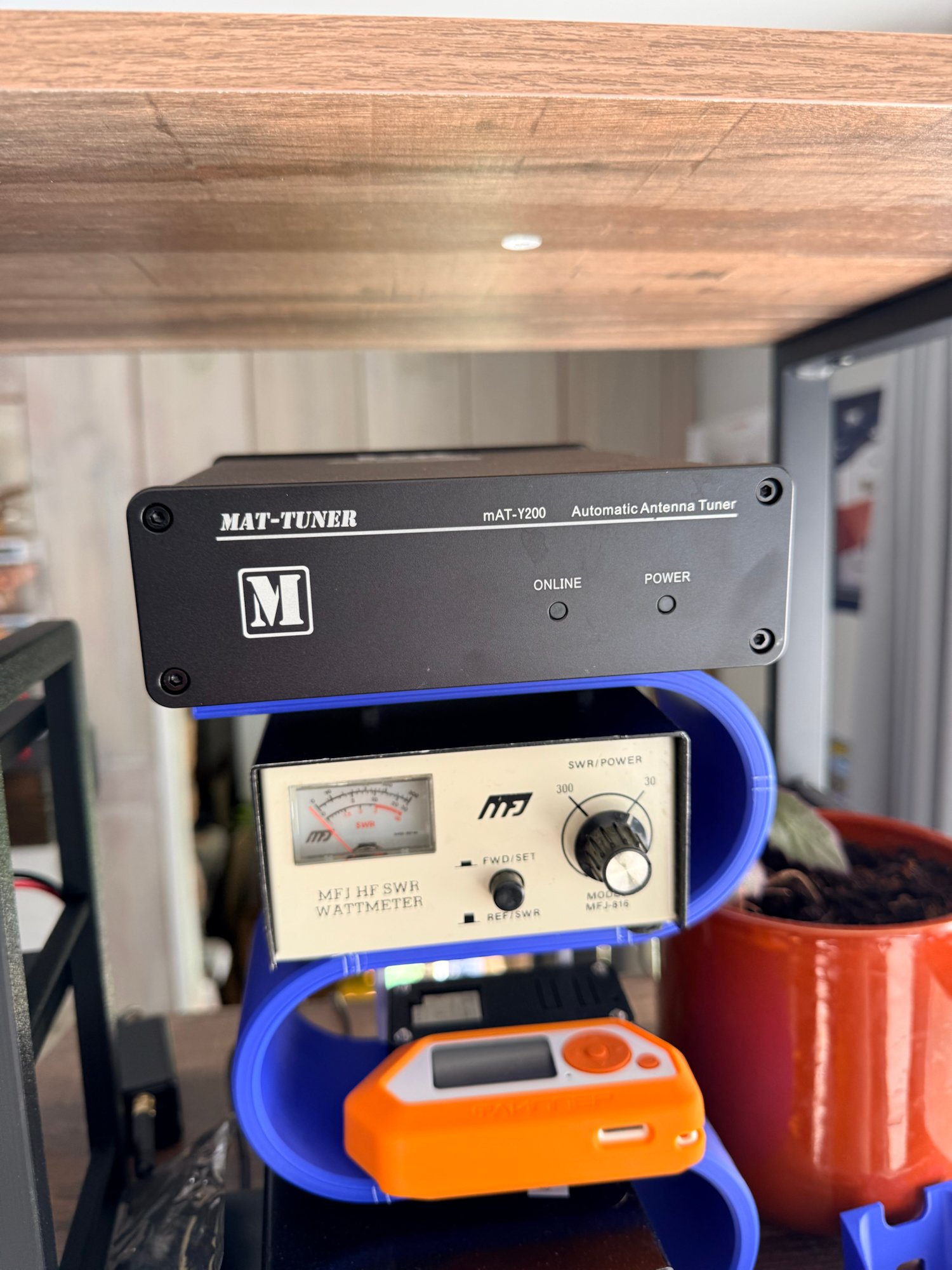
    MAT-Y200 automatic antenna tuner in an amateur radio station
    A real MAT-Y200 automatic antenna tuner from my station. The tuner provides an impedance match for the transmitter; it does not physically retune the antenna.

    Where the tuner sits makes a difference

    A tuner located in the shack protects the radio and gives it a good match, but the coax between the tuner and antenna can still be operating at high SWR. A remote tuner mounted at or near the antenna feed point can transform the impedance before the signal travels through the coax. That can substantially reduce mismatch-related coax loss in systems where the untuned feed-point impedance is far from 50 ohms.

    This is one reason remote automatic tuners are popular with non-resonant wires and some portable or multiband installations.

    A practical portable example

    Suppose you set up a portable vertical on 40 meters and the analyzer shows 3.5:1 SWR. A tuner at the radio may easily make the transceiver see 1.2:1. You can transmit, and the radio is satisfied — but the coax between the tuner and the antenna still has the original mismatch.

    If instead you adjust the whip, coil, or radial system until the antenna itself is near resonance and presents a reasonable match, the feed line operates under easier conditions. The tuner may then need to make only a small correction, or no correction at all.

    The best way to think about a tuner

    Think of an antenna tuner as a matching network, not an antenna repair device. It is extremely useful when an otherwise workable antenna presents an impedance your radio does not like. It can broaden the usable range of an antenna system and make multiband operation much more convenient.

    But it cannot turn a poor radiator into a great one, recover power already lost as heat in the feed line, or replace good antenna design. Whenever possible, start with an efficient antenna, good feed line, solid connections, and a sensible installation. Then let the tuner do the job it was designed to do: provide the radio with the impedance match it needs.

    Roger Quintana, NJ2RQ — LuffyHamVault.com

    Further reading

    For deeper reading, see ARRL’s “More About Antenna Tuners” and “Feed Lines”, which explain the same distinction between matching the transmitter and changing the actual SWR on the antenna side of the tuner.