There is plenty happening in amateur radio right now — and this week has a little bit of everything: a major WRTC scoring shake-up, fresh Kenwood mobile-radio activity, a new Yaesu FTX-1 firmware package, and several September operating events that are worth putting on your calendar.
WRTC 2026 Results Were Revised After Four Teams Were Disqualified
One of the biggest stories in competitive amateur radio this week came from the World Radiosport Team Championship. ARRL reported on September 3 that the official WRTC 2026 results were revised after four teams were disqualified following an investigation into rule violations involving station identification and fraudulent multiplier contacts.
The revised top three placed MB5O first, MB4G second, and MB1T third. Whether you are a serious contester or simply follow the sport, this is a significant story because WRTC is widely regarded as one of amateur radio’s premier operating competitions. The full details are available in the September 3 ARRL Letter.
Portable and competitive operating continue to drive interest across the amateur-radio community.
Kenwood’s TM-D750 Is One of the Most Interesting New Mobiles to Watch
Kenwood’s new TM-D750 family is now appearing across the company’s official amateur-radio support pages. Kenwood lists the TM-D750 as a 144/430 MHz digital dual-band mobile with APRS, D-STAR, Bluetooth and microSD support. The company also released its MCP-D750 memory-control software and a new virtual COM-port driver in late August.
For U.S. hams, the important point is that official support infrastructure for the TM-D750A/E is now live, even though pricing and market availability can differ by country. This is a radio worth watching closely if you want a modern APRS/D-STAR mobile. See Kenwood’s official amateur software page for current support files.
Yaesu FTX-1 Firmware Gets a Fresh Update
Yaesu’s official FTX-1 series page lists a firmware update dated August 28, 2026. The package updates the DISPLAY, MAIN, DSP and optional power-amplifier firmware, and Yaesu says it adds support for ADMS-19 memory-editing software along with additional bug fixes.
FTX-1 owners should confirm their current firmware versions before updating and follow Yaesu’s update instructions carefully. The latest information is posted on Yaesu’s official FTX-1 series page.
September VHF Contest and New Jersey QSO Party Are Coming Up
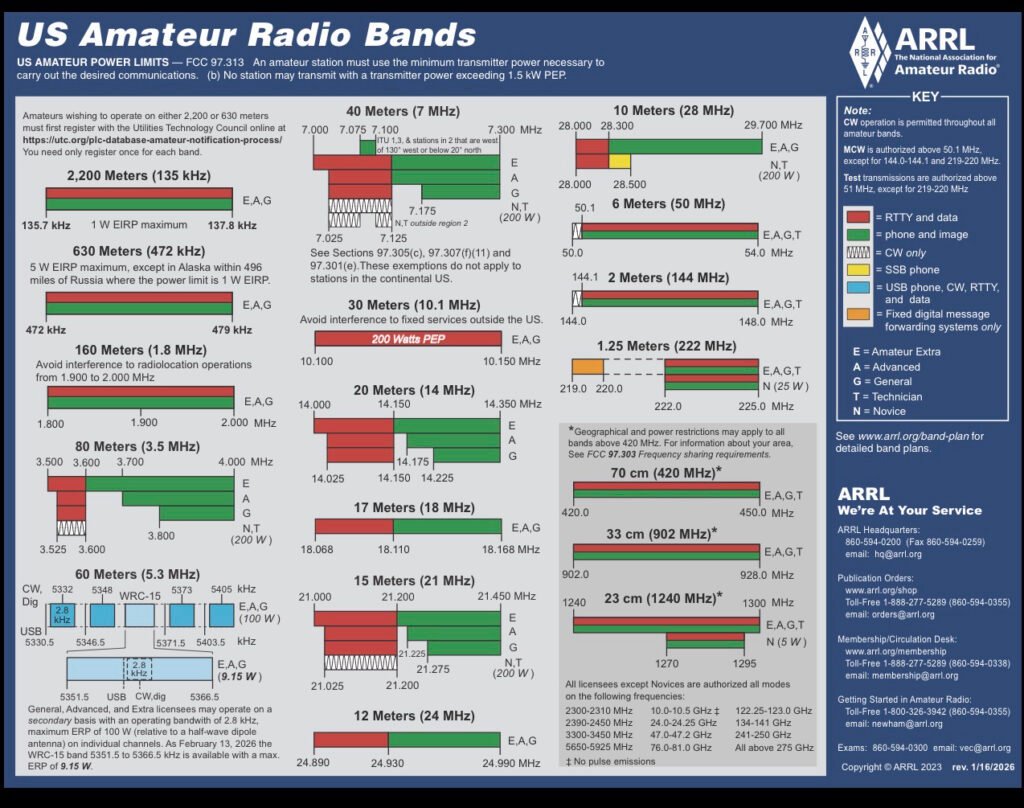
The ARRL September VHF Contest runs September 12-14, 2026. Operators can use legal modes above 50 MHz, and ARRL notes that FM-only entrants may now count contacts on 902 MHz and 1.2 GHz in addition to the lower VHF/UHF bands.
For operators in New Jersey, the September 12-13 weekend is especially busy because the New Jersey QSO Party is also on the radiosport calendar. That makes next weekend a good opportunity to put both HF and VHF/UHF stations on the air, test antennas, and make some contacts from home or portable locations.
Three areas are worth following over the next several weeks: new mobile and portable radio availability, firmware and software releases, and the fall operating calendar. There are also active manufacturer promotions running through September on selected Yaesu and Icom amateur-radio products, so shoppers should compare current dealer pricing before buying.
At Luffy Ham Vault, the goal is to separate real news from rumor and focus on developments that actually matter to operators. If a new radio, firmware release, event or regulatory development is confirmed by an official source, we will highlight what changed and why it matters on the air.
Sources: ARRL, Kenwood, and Yaesu official websites. Information checked September 6, 2026.
If you’ve spent any time scanning the local bands in New Jersey, you’ve almost certainly keyed up the W2NJR repeater network. But who is the voice and the vision behind the gear? I had the pleasure of meeting up with Eric, K2CB, who was first licensed in 1984 at the age of 15. His journey in radio began with CB in his teens—a passion that eventually evolved into him becoming the architect of one of the most reliable and iconic linked repeater systems in the region.
In this interview, we peel back the layers of the hardware, the history, and the sheer dedication required to maintain a statewide network that keeps our amateur radio community connected
POTA is an international award program that encourages amateur radio operators to take their gear out of the home shack and into the wild. It turns public parks into temporary radio stations, promoting both the hobby and our beautiful public lands.
The community is split into two main roles (and many operators do both!):
Activators: The portable operators who pack up their transceivers, batteries, and temporary antennas, head into a designated park, and set up a station to make contacts.
Hunters: The operators sitting comfortably at home (or in their mobile rigs) trying to “hunt” down the activators and log a contact with them in the park.
🔍 The Rules are Simple
The structure is straightforward, which is exactly why it’s so popular:
To successfully activate a park, an operator must make at least 10 unique contacts (QSOs) during their stay.
Contacts can be made using any amateur radio band and any mode—whether that’s traditional voice (SSB), Morse code (CW), or digital modes like FT8 and FT4.
Everything is tracked via an online leaderboard, where both activators and hunters can earn certificates, clean up awards, and track their stats over time.
❓ Why Do People Love It?
1. Emergency Preparedness: It forces you to build a highly efficient, portable “go-kit.” If you can set up a station on a picnic table in 15 minutes and log contacts across the country using battery power, you’re ready for real-world deployment when the grid goes down.
2. The Community: POTA is incredibly welcoming. Hunters are always eager to help an activator get their 10 contacts, and it’s a fantastic way to introduce curious park passersby to the magic of radio.
3. The Challenge: Leaving the comfort of a permanent home antenna means dealing with the elements, managing battery life, and learning how to optimize portable antennas like vertical whips or wire dipoles on the fly.
Whether you’re looking to get some fresh air with your rig or want to chase some rare state parks from the comfort of your own desk, POTA is a phenomenal way to play radio.
👇 Are you a Hunter or an Activator? Drop your favorite park or your callsign in the comments below!
Real-World Review: The Hy-Gain AV-680 Patriots Vertical Antenna
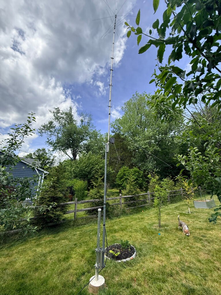
If you are looking for a true multi-band HF antenna that delivers solid performance without a massive backyard footprint, the Hy-Gain AV-680 Patriots vertical is bound to cross your radar. Covering 9 bands from 80 meters all the way up to 6 meters, it promises a lot on paper.
But how does it handle during assembly, tuning, and real-world DX operating? Let’s dive into the details.
Overview and Key Features
The AV-680 is a no-radial, 9-band vertical antenna utilizing individual quarter-wave stubs for the higher bands (6m through 17m) and matching networks/end-loading for the lower bands (20m, 30m, 40m, and 80m).
Frequency Coverage: 80, 40, 30, 20, 17, 15, 12, 10, and 6 Meters.
No Radials Required: Great for smaller yards or neat installations.
Power Handling: Full legal limit on most bands.
Feedpoint: Includes a robust matching network housed in a weather-resistant box at the base.
Assembly & Mechanical Design: A Multi-Stage Project
Let’s be honest upfront—this is not an antenna you assemble in 20 minutes between radio contacts. The AV-680 is a mechanical puzzle with a lot of moving parts, stubs, and hardware.
The Build Experience
The Manual: You’ll want to follow the documentation closely. Pay precise attention to the element measurements before clamping everything down.
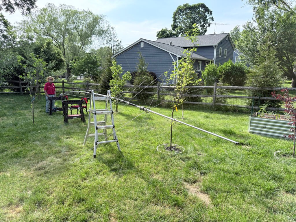
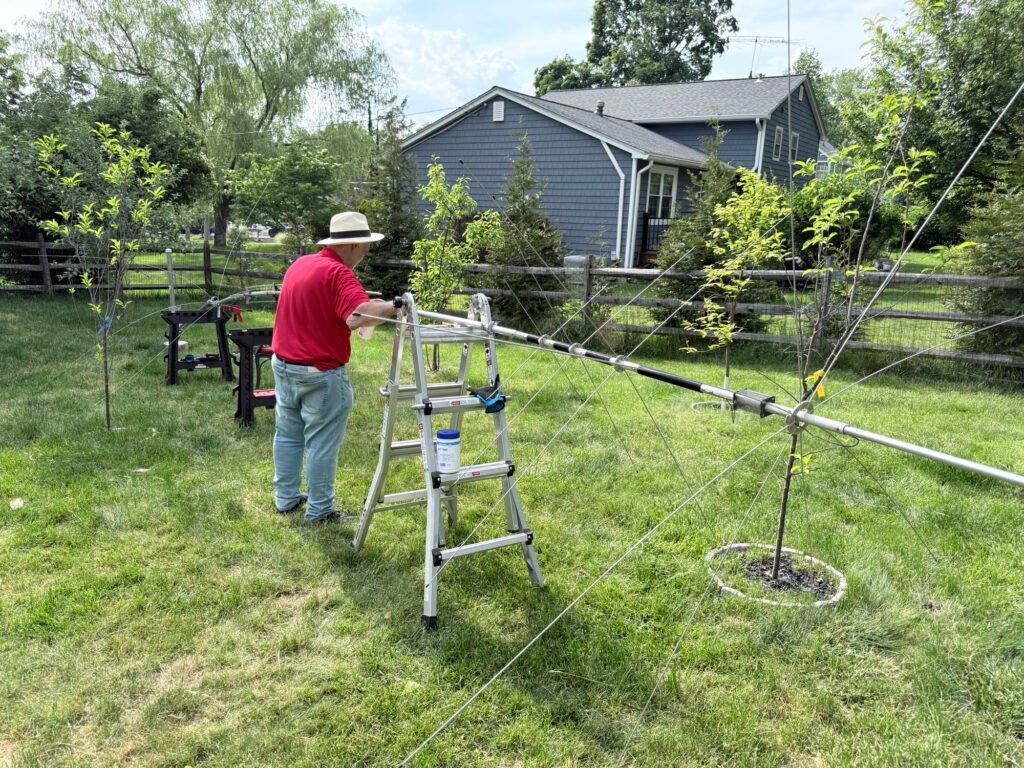
Work Space: Do yourself a favor and set up a solid staging area. Using portable work tables and a step ladder in the yard makes managing the long aluminum sections and delicate wire stubs significantly easier during construction.
Build Quality: The heavy-duty aluminum sections feel solid once locked together. The matching network box at the base is well laid out, featuring high-quality toroidal transformers secured tightly with heavy-duty zip ties to prevent rattling or shifting over time.
Pro-Tip: Keep some anti-seize aluminum paste handy for the joints, and take your time adjusting the individual band stubs during the initial build to save yourself trips up and down the ladder later.
Mounting and Grounding
Because the AV-680 uses an efficient counterpoise system at the base (creating a neat, starburst-like ring of capacity spokes), it doesn’t require a massive web of radial wires killing your lawn.
Mounting it to a heavy-duty, insulated steel ground post or tilt-base setup makes the final erection a smooth process. Even with its height, a well-anchored base keeps the vertical incredibly stable. For safety and lightning protection, tying the mounting mast into a dedicated ground rod system is highly recommended.
Tuning and Performance: A DX Machine
Once the antenna is vertical and hooked up to an analyzer, the magic of the AV-680 becomes clear.
SWR and Bandwidth
Thanks to the broad-band matching network, the SWR across the higher bands (10m–20m) is exceptionally clean, often dropping well below 1.5:1 right out of the box if your initial measurements were precise. On 40m and 80m, the bandwidth is understandably narrower—a common trait for any shortened vertical—but it places the resonant sweet spot exactly where you need it for digital modes or specific phone windows.
On the Air
With its low angle of radiation, the AV-680 absolutely shines for long-distance propagation.
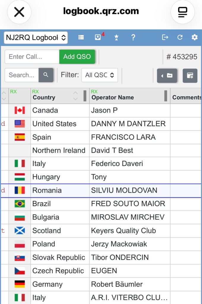
If you track your contacts on a digital logbook (like QRZ), watching the globe light up is incredibly satisfying. Even on modest power or running digital modes like FT8 and FT4, you can routinely pick up solid, multi-band openings and bag effortless contacts across Europe (Germany, Italy, Czech Republic, Romania), South America (Brazil), and over the pond to the UK. It holds its own beautifully against standard dipoles when it comes to pulling weak DX signals out of the noise.
The Verdict
What We Like:
Incredible Band Coverage: True 9-band capability from a single feedline.
No Radial Footprint: Ideal for maintaining a clean yard or dealing with space restrictions.
Excellent DX Performance: Low take-off angle punches through to distant continents easily.
Rugged Base matching: Well-engineered matching network built to handle real power.
What to Keep in Mind:
Intense Assembly: Requires patience, precise measurements, and a few hours of dedicated yard work to assemble properly.
Narrow 80m/40m Bandwidth: Expect to use an internal or external tuner if you like to wander far from your initial resonant frequency on the lower bands.
Final Thoughts
The Hy-Gain AV-680 is a phenomenal investment for any amateur radio operator wanting maximum band flexibility without putting up a massive tower or an array of wire antennas. Once you get past the intricate assembly phase and get it up in the air, its performance on the airwaves speaks for itself. It’s an absolute DX collector.
If you’ve spent any time looking into modern ways to experience amateur radio, you’ve likely stumbled upon a platform called HamSphere. For many beginners or those without a permanent rig setup, it’s a fascinating gateway into the hobby.
But what exactly is it? If you look at a registered call sign like 2HS22392, you’ll notice it looks a bit different from a traditional government-issued amateur radio call sign. That is because it’s a dedicated HamSphere call sign.
To clear up the confusion for anyone looking to jump in, let’s break down exactly what HamSphere is—and what it isn’t.
What HamSphere IS
At its core, HamSphere is a highly advanced, cloud-based amateur radio simulator. It allows users to operate a virtual shortwave transceiver from a PC, smartphone, or browser, complete with a realistic community experience.
A Realistic Ionospheric Simulation: HamSphere doesn’t just let you chat over the internet like a standard VoIP app (like Skype or Discord). It uses a complex mathematical model driven by real-world solar data (Sunspot Numbers and Solar Flux Index) to simulate actual HF propagation. This means you experience real-world signal fading, skipping, and atmospheric noise.
An Incredible Learning Tool: For aspiring hams or shortwave listeners (SWLs), it is an excellent sandbox. You can practice “mic skill,” learn standard radio etiquette, practice Morse Code (CW), and master how to tune a transceiver without the fear of accidentally violating FCC (or local regulator) rules.
A Sandbox for Customization: The platform operates on a modular “plug-in” system. You can build out your virtual shack by adding different band scopes, waterfalls, and an array of over 125 virtually deployed antennas (Yagis, dipoles, verticals) that react realistically based on where you point them.
An Inclusive Global Community: You don’t need an official government license to join. Unlicensed enthusiasts are granted a unique HamSphere call sign (like the 2HS prefix), allowing them to log contacts, fill out a virtual logbook, and exchange digital QSL cards with thousands of operators across hundreds of countries.
What HamSphere IS NOT
While it does an incredible job of mimicking the hobby, it’s important to understand its limitations so you have the right expectations.
It Is NOT Real RF (Radio Frequency): When you press the Push-to-Talk (PTT) button on HamSphere, you are not transmitting electromagnetic waves into the sky. Your voice travels strictly over the internet via VoIP. The only “radio” involved is the Wi-Fi or cellular data connecting your device to the internet.
It Is NOT Connected to the Real Amateur Bands: You cannot use HamSphere to communicate with an operator sitting in front of a physical, hardware HF rig (like an Icom or Yaesu) transmitting on the actual physical airwaves. You can only communicate with other users logged into the HamSphere network.
It Is NOT Free (Beyond the Trial): While it offers a trial period, full access operates on a subscription model (around €32 or $30–$40 USD per year). Furthermore, many advanced features—like specific high-gain antennas, custom filters, or waterfall displays—are sold separately as virtual plug-ins.
It Is NOT a Government License Substitute: Having a HamSphere call sign is wonderful for the simulator, but it does not grant you the legal right to operate physical amateur radio equipment on real-world frequencies.
The Verdict: Who is it for?
HamSphere is the perfect bridge for two types of people:
1 The Curious Beginner: If you want to experience the thrill of hunting DX (long-distance contacts) and navigating the unique quirks of shortwave radio without spending thousands of dollars on physical gear and antennas.
2 The Restricted Ham: If you are a licensed operator living in an apartment building with strict HOA rules that forbid antennas, HamSphere offers a way to stay active in the culture of the hobby.
It may be a simulation, but the conversations, the friendships, and the practice you get on the virtual airwaves are entirely real.
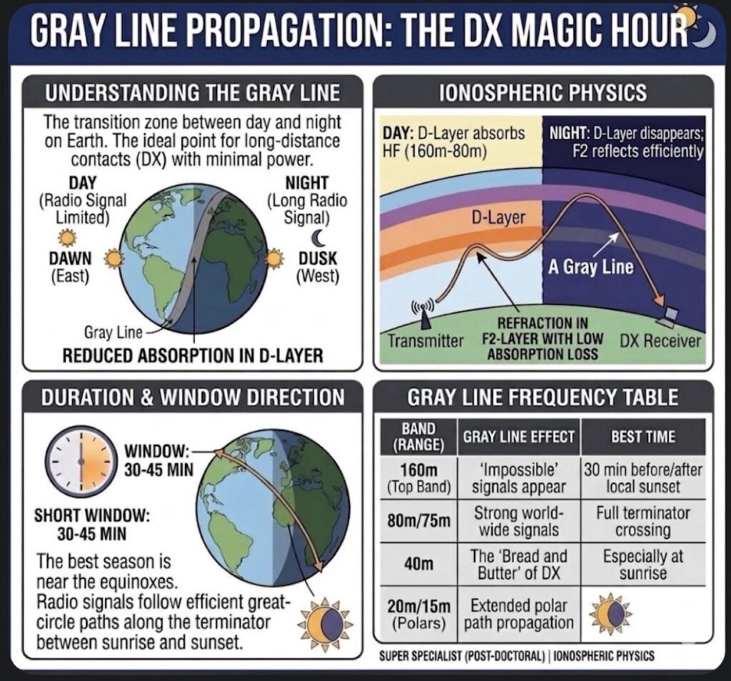
If you’ve ever been on the air around sunset or sunrise and noticed signals from the other side of the planet suddenly booming in—as if someone flipped a secret switch—you’ve experienced the Gray Line. In the ham radio world, we call this the “DX Magic Hour,” and for good reason. It’s that brief, 30-to-45-minute window where the rules of physics seem to bend in our favor.
But what’s actually happening up there in the ionosphere?
The Science of the “Exterminator”
The Gray Line is essentially the Terminator—the moving boundary that separates day from night. The magic happens because of a perfect atmospheric “hand-off.” During the day, the D-Layer is the enemy of low-band DX; it sits low in the atmosphere and gobbles up your signals on 160m, 80m, and 40m.
As the sun sets, the D-Layer disappears almost instantly because it needs direct sunlight to stay ionized. However, the higher F2-Layer is much thinner and takes a lot longer to lose its charge. For a short time, you have a clear path where your signal can bounce (refract) off the F2-Layer with almost zero absorption from the D-Layer. It’s like a high-speed tunnel for radio waves.
How to Ride the Wave
As you can see on the card I put together, the signals follow Great Circle paths along this twilight zone. This isn’t just for the “Top Band” (160m) enthusiasts.
On 40m: This is the “bread and butter” of Gray Line work. You can often work stations halfway around the world with surprisingly low power.
On 160m and 80m: You’ll hear “impossible” signals. If you’re in South America at sunset, you might find yourself talking to someone in Asia who is just seeing their sunrise.
On 20m and 15m: It opens up unique polar paths that are usually closed during the dead of night or the heat of the day.
Tips for the Shack
The window is short, so you have to be ready. I always recommend using a real-time Gray Line map or a tool like VOACAP. The peak usually hits when both you and the DX station are sitting right on that terminator line. You’ll hear the noise floor drop, the signals rise, and for a few minutes, the world feels a lot smaller.
Next time you see the sky turning that deep orange or purple, don’t just admire the view—get on the rig. The Gray Line is nature’s own signal booster, and it’s waiting for you to jump in.
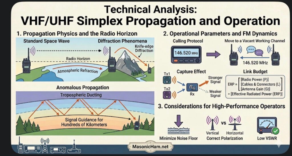
Simplex operation represents the fundamental Single-Frequency Half-Duplex communication mode. Unlike duplex systems that utilize frequency offsets and repeaters, simplex relies entirely on the direct link between two stations. This makes it the ultimate test of a radiant system’s efficiency and the operator’s mastery of the local RF environment.
Propagation Physics and the Radio Horizon
In the VHF and UHF bands, communication is primarily governed by line-of-sight space wave propagation.
✔️Atmospheric Refraction: The radio horizon is slightly longer than the visual horizon. This occurs because variations in atmospheric density cause radio waves to undergo a subtle curvature, allowing the signal to follow the Earth’s curvature for an additional distance.
✔️Diffraction Phenomena: Success in simplex within obstructed areas depends on knife-edge diffraction, where the signal “bends” upon hitting sharp obstacles such as mountain ridges or the tops of buildings.
✔️Anomalous Propagation: Events such as tropospheric ducting, caused by thermal inversions, can create atmospheric layers that guide the signal for hundreds of kilometers, enabling simplex contacts that would be impossible under normal conditions.
Operational Parameters and FM Dynamics
✔️Calling Protocol: The 146.520 MHz frequency acts as a meeting point. Standard operational protocol dictates that, after initial contact, operators should move to a vacant working channel, preserving the calling frequency for new requests.
✔️Capture Effect: A vital characteristic of the FM mode in simplex is the capture effect. The receiver will process only the signal that arrives with the highest intensity, suppressing weaker signals on the same frequency. This requires technical coordination to prevent more powerful stations from “clobbering” ongoing communications.
✔️Link Budget: Without the gain of a repeater, performance depends exclusively on Effective Radiated Power (ERP). This is the result of the actual power leaving the radio, subtracting attenuation losses in cables and connectors, and adding the directional gain of the antenna used.
Considerations for the High-Performance Operator
Advanced simplex operation requires minimizing the Noise Floor. In point-to-point scenarios, the Signal-to-Noise Ratio is the determining factor. Using the correct polarization (generally vertical for mobile stations and horizontal for sideband DX) and ensuring a low Voltage Standing Wave Ratio (VSWR) are fundamental to guaranteeing communication integrity at extreme distance limits.
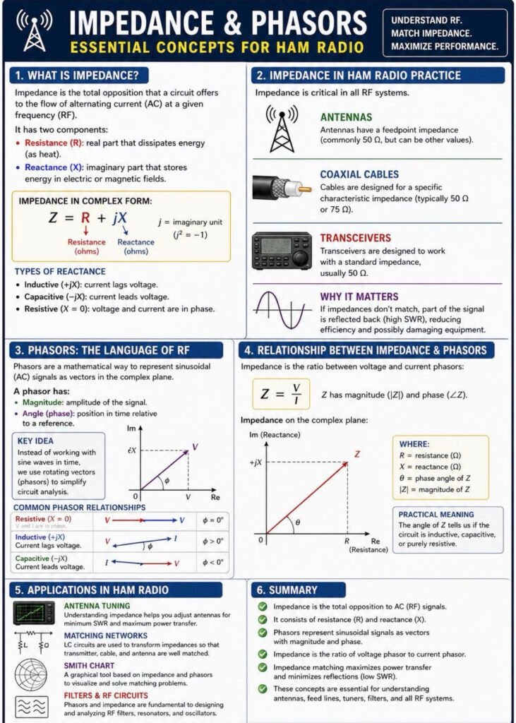
If you’ve ever tried to tune an antenna or wondered why your radio isn’t delivering full power to the air, you’ve already bumped into impedance—even if you didn’t call it that. In simple terms, impedance is how a circuit “pushes back” against an RF signal. It’s not just plain resistance. It also includes effects from capacitors and inductors, which store and release energy as the signal alternates. That’s why, in radio work, impedance is treated as a combination of a real part (which dissipates power) and a reactive part (which shifts energy back and forth). This idea is standard in basic circuit theory and RF engineering references like ARRL handbooks and classic textbooks.
Now, where things get interesting is when signals are constantly changing, like they do in radio. Instead of tracking every rise and fall of a sine wave over time, engineers use a shortcut called phasors. Think of a phasor as a rotating arrow that represents the signal’s size and its timing (phase) all at once. This approach is widely used in electrical engineering because it makes analyzing AC circuits much easier, especially when you’re dealing with filters, amplifiers, or antennas.
So how do these two ideas connect in real ham radio practice? Impedance depends on how voltage and current relate to each other, and in RF circuits they’re often not perfectly “in sync.” That phase difference—whether current lags or leads voltage—is exactly what phasors help visualize. For example, an inductive load causes current to lag behind voltage, while a capacitive load does the opposite. These behaviors are well established in standard AC circuit analysis and are critical when working with tuned circuits or matching networks.
Bringing this back to your shack: when your antenna system is properly matched—typically to 50 ohms for most transceivers—power flows efficiently from the radio into the antenna. If the impedance doesn’t match, part of that signal reflects back, increasing SWR and reducing performance. That’s why understanding impedance and using tools that rely on phasor concepts—like antenna analyzers—makes such a big difference in getting the most out of your station.
Once you see impedance as more than just a number, and phasors as a practical way to understand signal behavior, a lot of RF concepts start to click. It’s not abstract math—it’s exactly what’s happening every time you key the mic.
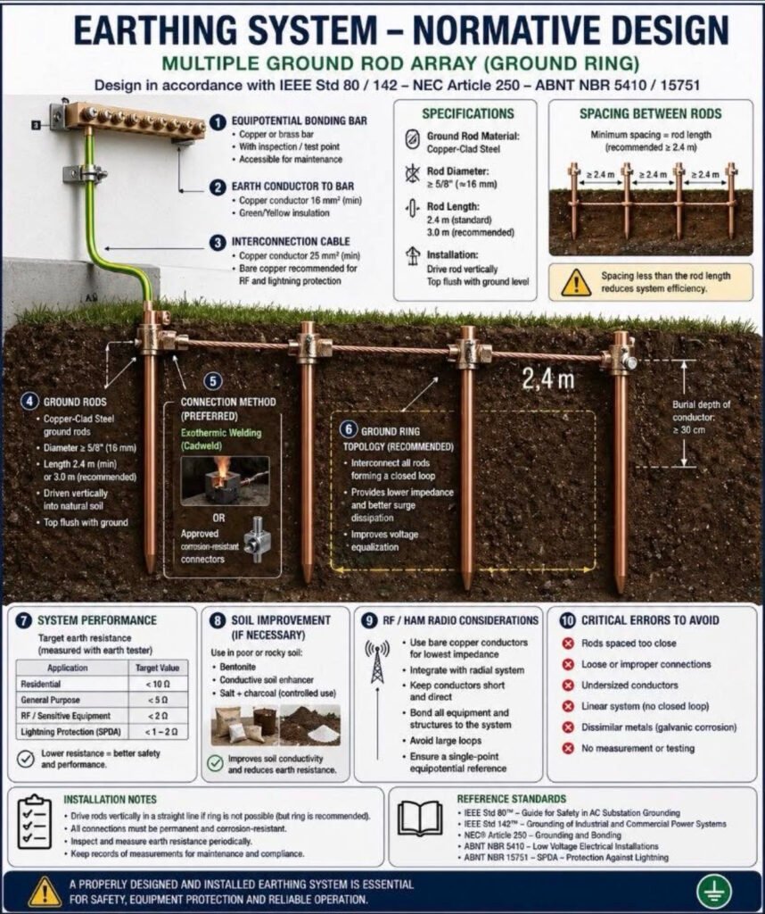
When you look at a grounding system like this—multiple rods connected in a ring—it might seem like overkill at first. But in ham radio, this is exactly the kind of setup that separates a “working station” from a reliable and safe station.
In practice, grounding isn’t just about sticking a rod in the ground. It has three very clear roles: protecting you from electrical faults, safely dissipating lightning energy, and providing a stable reference for RF currents . When you build a ground ring with several interconnected rods, you’re essentially creating a low-impedance path that spreads energy into the soil much more efficiently than a single rod ever could.
That makes a real difference on the air. A well-designed grounding system helps reduce unwanted noise and interference, improves signal stability, and keeps RF where it belongs—out of your shack and in the antenna . Especially with vertical antennas, having a proper return path to ground is critical for efficiency; otherwise, part of your transmitted power is simply lost as heat instead of being radiated . The “ring” approach also follows good engineering practice. By bonding all rods together, you avoid dangerous voltage differences between points during faults or lightning events, something emphasized in professional grounding standards and widely adopted in serious installations.
In the end, this kind of grounding system isn’t about complexity—it’s about consistency. Everything shares the same reference, energy has a clear path to earth, and your station behaves the way it should. And once you’ve operated with a properly grounded setup, it’s hard to go back.
Whether you’re working a digital pile-up on FT8 or just trying to jump on a Zoom call from a rural area, we all know that a stable, high-speed internet connection is the backbone of modern life. Today, I want to dive deep into a piece of technology that has completely redefined what “being connected” means: Starlink.
How It Works: Space-Age Networking
We’ve all seen traditional satellite internet—it was often slow, laggy, and prone to dropping out. That’s because those satellites sit in Geostationary Orbit (GEO), about 22,000 miles away.
Starlink is different. It utilizes a Low Earth Orbit (LEO) constellation. Here’s the breakdown:
• Distance: These satellites are only about 340 miles above us. This shorter distance means significantly lower latency (ping), making it feel just like a fiber connection.
• The Phased Array: Your Starlink dish isn’t a “dish” in the old sense; it’s a sophisticated phased-array antenna. It doesn’t physically move to track a single satellite; instead, it uses electronic beamforming to “hand off” your signal from one satellite to the next as they zip across the sky at 17,000 mph.
• Global Backhaul: These satellites talk to ground stations (gateways) connected to the world’s fiber backbone, and newer models even use space-lasers to talk to each other, allowing for internet coverage in the middle of the ocean or the deepest wilderness.
The Starlink “Home” (Standard Gen 3): The Residential Powerhouse
For the home QTH, the Gen 3 Standard kit is the current gold standard.
• Performance: It’s designed for high-demand households. We’re talking 4K streaming, heavy downloads, and enough bandwidth to run a full shack of networked gear without breaking a sweat.
• Field of View: With a 110-degree field of view, it’s incredibly resilient against minor obstructions.
• Asset to the Home: It provides a redundant “backdoor” to the internet. If a storm knocks out the local cable lines, your Starlink stays up as long as you have power.
The Starlink Mini: The Ultimate Portable Asset
As many of you know, I’m a big fan of portable gear, and the Starlink Mini is a masterpiece of engineering.
• All-in-One: The router is built right into the dish. It’s roughly the size of a thick laptop and fits easily in a backpack.
• Low Power: It draws significantly less power (25-40W) than the home unit, meaning you can run it off a portable battery station or even a DC car adapter for hours.
• Off-Grid Comms: For those of us involved in AREDN or emergency mesh networking, the Mini is the perfect “I-Gate.” You can drop into a remote site, deploy the Mini in two minutes, and provide a high-speed internet gateway to an entire local mesh network.
Why It’s a Great Asset for You
1. True Portability: Take your “home” internet to the campsite, the park, or a mobile emergency command center.
2. Weather Resilience: Both units feature an internal heating element to melt snow and ice—essential for those New Jersey winters!
3. No Contracts: The ability to pause and unpause service (especially on the Roam plans) makes it perfect for seasonal hams or weekend adventurers.
In short, Starlink isn’t just about “getting online”—it’s about the freedom to be connected anywhere on the planet. Whether you’re at the desk or in the field, it’s a tool that every modern communicator should consider.
There is a unique kind of magic in amateur radio that never gets old. This morning, I sat in my shack, sipped a coffee, and watched my screen as a station in New Zealand confirmed a contact with me. Then Russia. Then Japan.
The kicker? I wasn’t using a massive tower. I was using an inexpensive wire antenna in my front yard and a mode called FT8.
The best part about FT8 is its accessibility. You don’t need the latest $3,000 transceiver to do this. Whether you have a brand-new SDR or a 30-year-old “boat anchor,” you can be chasing DX across the globe by lunchtime.
What is FT8?
FT8 is a “weak-signal” digital mode. Because the software uses advanced digital signal processing, it can “hear” signals that are 10-15 dB below the noise floor—signals your ears would never even register. This makes it the ultimate “equalizer” for hams with modest setups or restricted yards.
1. The Essential Gear
To get on the air, you need three core components:
• The Radio: Any SSB-capable transceiver will work.
• The Antenna: A simple End-Fed Half-Wave (EFHW) or a dipole in your yard is perfect. Because FT8 is so efficient, height is less critical than it is for voice.
• The Computer: Any modern laptop or desktop (Windows, Mac, or Linux). Even an old “shack PC” has enough power for this.
2. Bridging the Gap: The Interface
How you connect your radio to your computer depends on your rig:
• Modern Rigs (The USB Way): Radios like the Yaesu FT-710 or Icom 7300 have built-in sound cards. You just need a single USB cable and the correct drivers.
• Classic Rigs (The Interface Way): If your radio doesn’t have a USB port, you’ll need an external interface like a SignaLink USB or a Digirig. These devices act as a “middleman,” translating the audio from your radio’s accessory port into data your computer can understand.
3. Technical Setup & Software
Download WSJT-X (the gold standard). Once installed, the setup follows a simple logic:
1. Audio: Tell the software which sound card (internal or external) to use for Input and Output.
2. CAT Control: This allows the software to change your radio’s frequency. If your radio is too old for CAT, you can use VOX (Voice Operated Exchange) to trigger the transmitter.
3. Time Sync: FT8 relies on precise 15-second windows. If your PC clock is off by more than a second, you won’t decode anyone. Use a free tool like NetTime to keep your clock perfectly synced.
4. Best Practices for a Clean Signal
• Watch Your ALC: This is the #1 rule. When transmitting, your ALC (Automatic Level Control) should be at zero. Overdriving the audio creates “splatter,” which ruins the waterfall for everyone else.
• Low Power is Plenty: You don’t need 100 watts. Most FT8 enthusiasts operate at 20-30 watts. It saves your final transistors and is more than enough to cross an ocean.
• Use “Fake It”: In the WSJT-X settings, enable Split Operation: Fake It. This keeps your signal in the cleanest part of your radio’s filters.
Why Get Involved?
FT8 isn’t about long conversations; it’s about the thrill of the hunt. It’s about seeing a map light up with signals from every continent and knowing that your modest front-yard wire is punching way above its weight class.
If you see NJ2RQ on the waterfall, give me a click and let’s exchange a 73!
When Iran’s digital infrastructure collapsed into a total blackout, the modern world learned a humbling lesson. For over 60 hours, the silence was absolute: government channels vanished, state media went dark, and public services flatlined. Yet, amidst the wreckage of a sophisticated cyberwar, a single frequency—7910 kHz—remained untouchable.
While the internet proved fragile, shortwave radio didn’t even flinch.
The Invisible Bridge
Twice a day, with surgical precision, a Farsi numbers station cut through the noise. It bypassed every firewall, ignored every jammer, and crossed every border without a single packet of data.
• Speed of Detection: Within minutes of the first pulse, global ham radio operators had identified, logged, and began analyzing the transmission.
• Zero Infrastructure: While world leaders scrambled to restore fiber optics, the shortwave community only needed a wire antenna and the sky.
• The Ultimate Fail-Safe: This wasn’t a nostalgic exercise; it was a demonstration of the most battle-tested communication method in history.
Why Shortwave Still Matters
The recent conflict in Iran served as a global proof of concept. When high-tech warfare wipes the digital slate clean, High Frequency (HF) radio remains the bedrock of survival.
“This is not a hobby. This is the only technology that remains standing when everything else fails.”
In an era of vulnerable clouds and kill-switches, the Iran blackout proved that the “old ways” aren’t just reliable—they are invincible. All you need is the right frequency and a piece of wire to hear the truth when the world goes silent.
Jack Phillips — the man Born April 11, 1887 — he celebrated his 25th birthday the day after Titanic departed. He was just a kid. The night it happened Bride had gone to bed early to relieve Phillips at midnight. The Titanic hit the iceberg at 11:40pm. Bride woke up, Phillips said they had struck something, and Captain Smith came in shortly after telling them to send out a distress signal. The SOS detail — this is gold At one point Bride half-jokingly told Phillips “Send SOS — it’s the new call, and it may be your last chance to send it.” Jack sent the first SOS signal ever at 12:45 AM, April 15, 1912. The dark irony Earlier that night Phillips had gotten so annoyed at constant ice warnings from another ship that he told their operator in Morse code to “shut up” so he could keep sending passenger messages. His last transmission Phillips typed out Titanic’s last message — “Come quick. Engine room nearly full.” — before going silent for good. How he died Harold Bride later said: “I will never live to forget the work of Phillips during the last awful 15 minutes. I suddenly felt a great reverence to see him standing there sticking to his work while everybody else was raging about.” Bride later saw Phillips’ body clinging to debris from the sunken ship. He died from exposure. His legacy The Titanic disaster led directly to the Radio Act of 1912, which required 24-hour radio service on ships and had the US adopt SOS as its standard distress call.
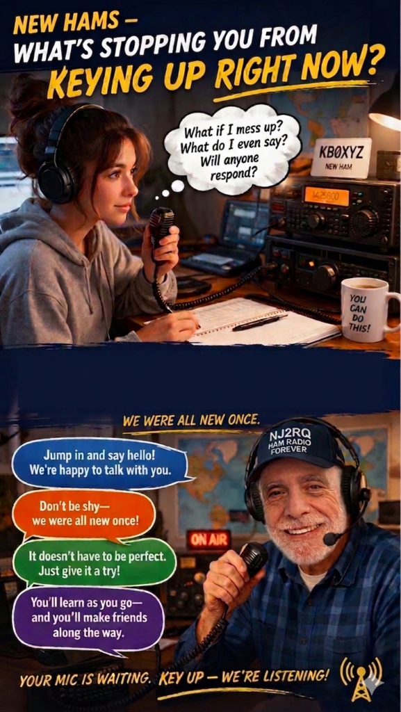
That thought bubble says it all. What if I mess up? What do I even say? Will anyone respond? 🤔 We’ve all been there. Every single one of us. I am new ham as well and this is what I learned on the air— the ham radio community is the most welcoming group of people you’ll ever talk to. Nobody is judging you. Everyone is rooting for you. 🙌 Your mic is waiting. Key up. 📻 73
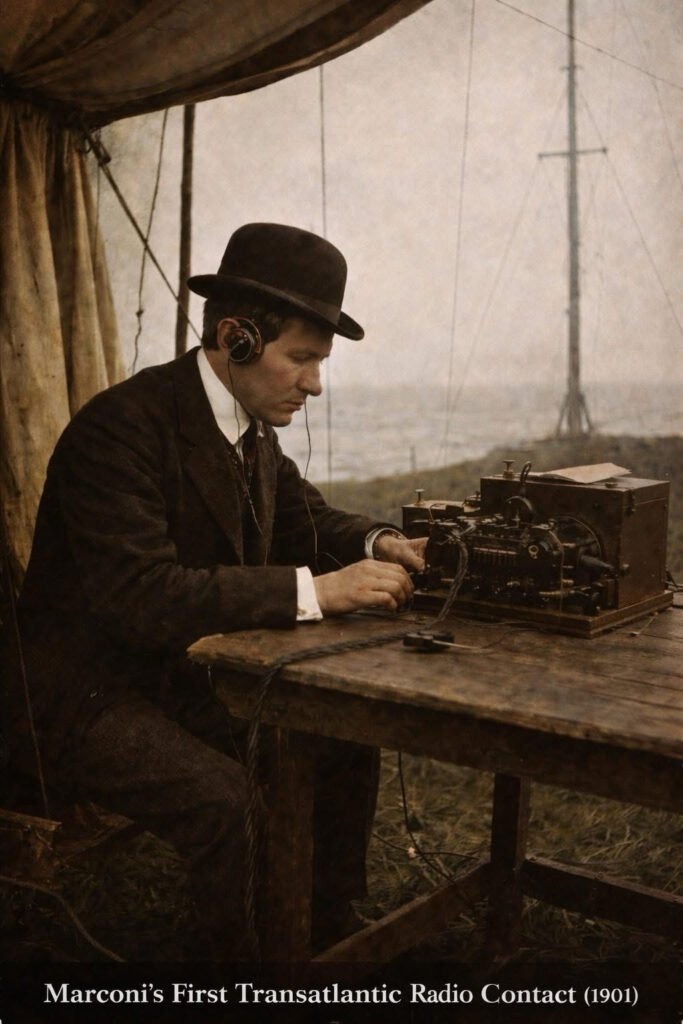
December 12, 1901. A cold, windswept cliff in Newfoundland, Canada. Guglielmo Marconi sat in a tent — headphones on, listening for something many believed simply wouldn’t work. Then he heard it. Three faint dots. ··· The letter “S” in Morse code. Transmitted from Poldhu, Cornwall, England — over 2,000 miles across the Atlantic. No wire. No cable. Just invisible waves crossing an ocean. Many scientists had doubted it would work. The Earth is curved, they argued. Radio waves travel in straight lines. They’ll shoot off into space and disappear. Marconi was 27 years old. He pressed forward anyway. What Marconi didn’t fully understand — and what science would later prove — was that the ionosphere reflects radio waves back to Earth. Nature itself was the relay station. He didn’t know why it worked. He just proved that it did. But Marconi wasn’t finished. On the windswept shores of Cape Cod, Massachusetts, he constructed one of the most powerful wireless stations on Earth — four towering 210-foot wooden masts rising from the sand dunes of South Wellfleet. On January 19, 1903, that station made history again. President Theodore Roosevelt and King Edward VII exchanged the first transatlantic wireless messages between world leaders — proof that this was no longer just a scientific experiment. It was the dawn of global communication. The site still exists today. The structures are long gone — lost to time and storms — but you can still walk those dunes and feel the weight of what happened there. Two stations. Two milestones. One unstoppable vision. And that vision is the grandfather of everything we do today. 🔹 Every DX contact you’ve ever logged 🔹 Every emergency net that saved lives 🔹 Every moonbounce, satellite pass, and digital mode 🔹 Every “59, you’re making it here from across the world” It all started with three dots in a freezing tent. Ham radio didn’t just survive 125 years. It evolved, adapted, and thrived — because the magic Marconi stumbled into that December morning never gets old. The ionosphere is still up there.
If you are looking to expand your knowledge of the airwaves, I cannot recommend these sessions enough. These Zoom presentations serve as a premier educational tool for everyone in the radio community—from the unlicensed curious to the seasoned Amateur Extra.
Whether you are just learning the basics or looking to dive into advanced technical theories, these lectures offer an accessible “amateur experience” at all levels. The insights shared here are invaluable for sharpening your skills and staying connected with the latest in radio technology and best practices.
Organized by Rol Anders (K3RA) and Tom Christovich (K3YH), the course covers a wide spectrum of specialized topics ranging from traditional modes to modern digital innovations.
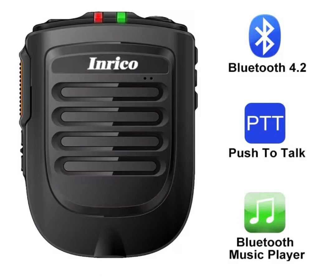
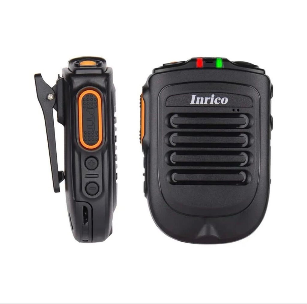
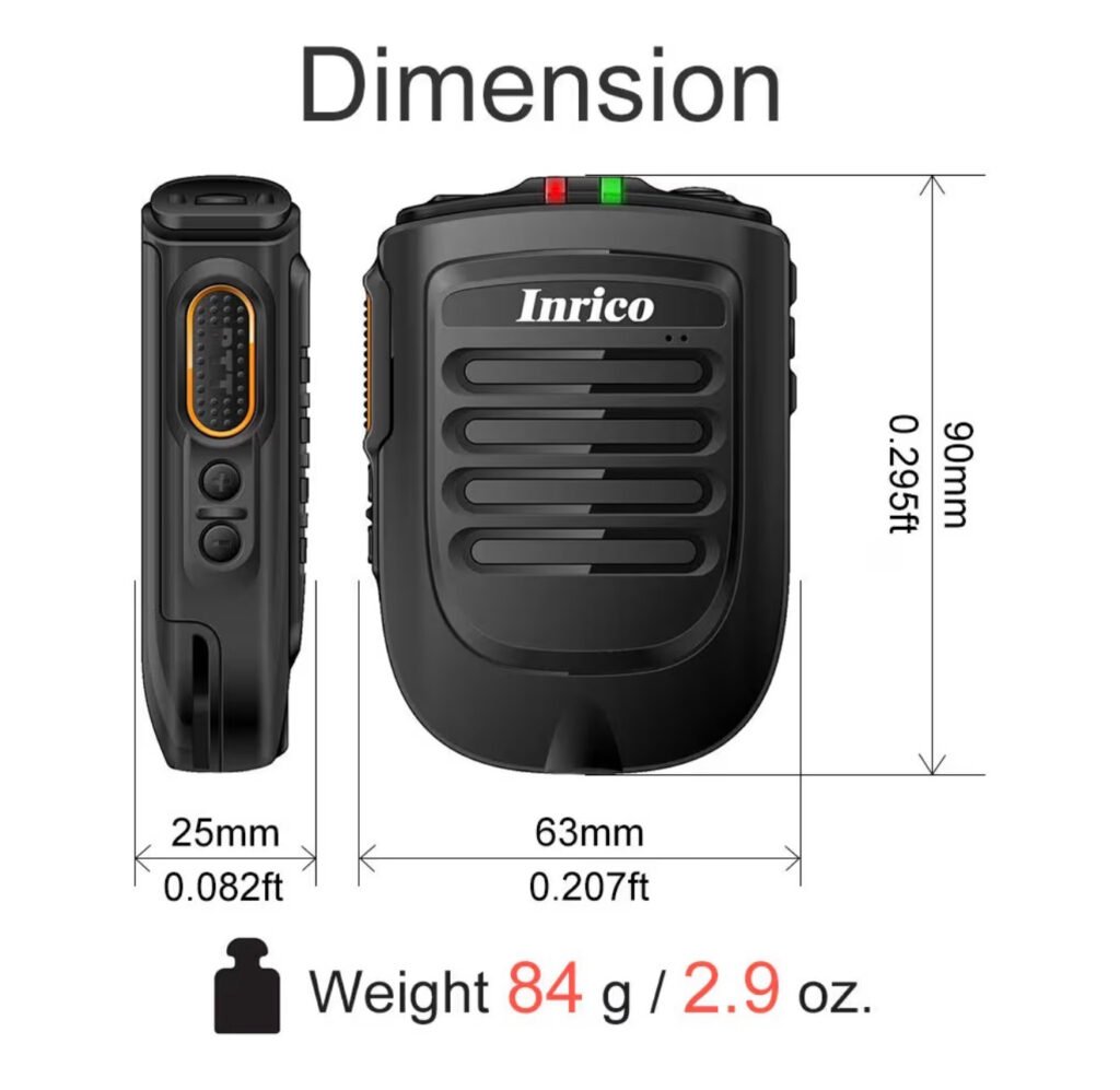
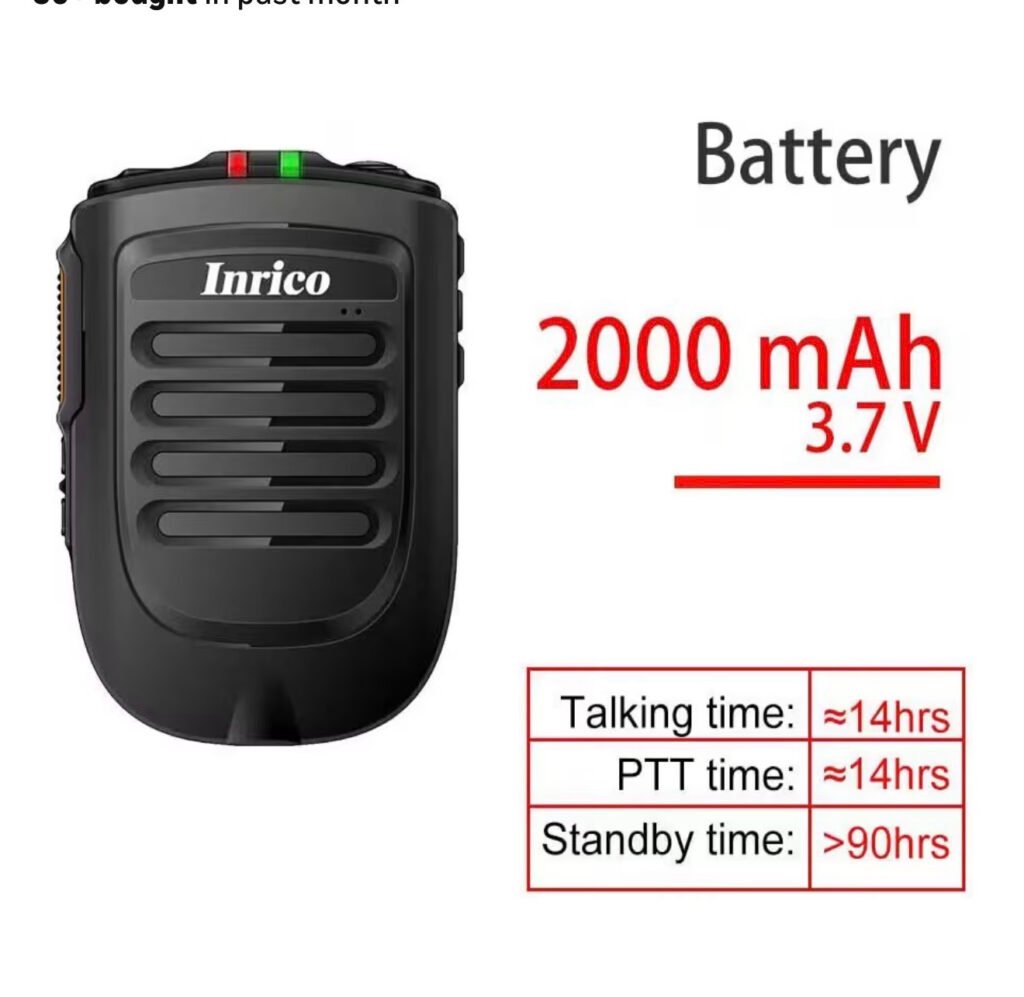
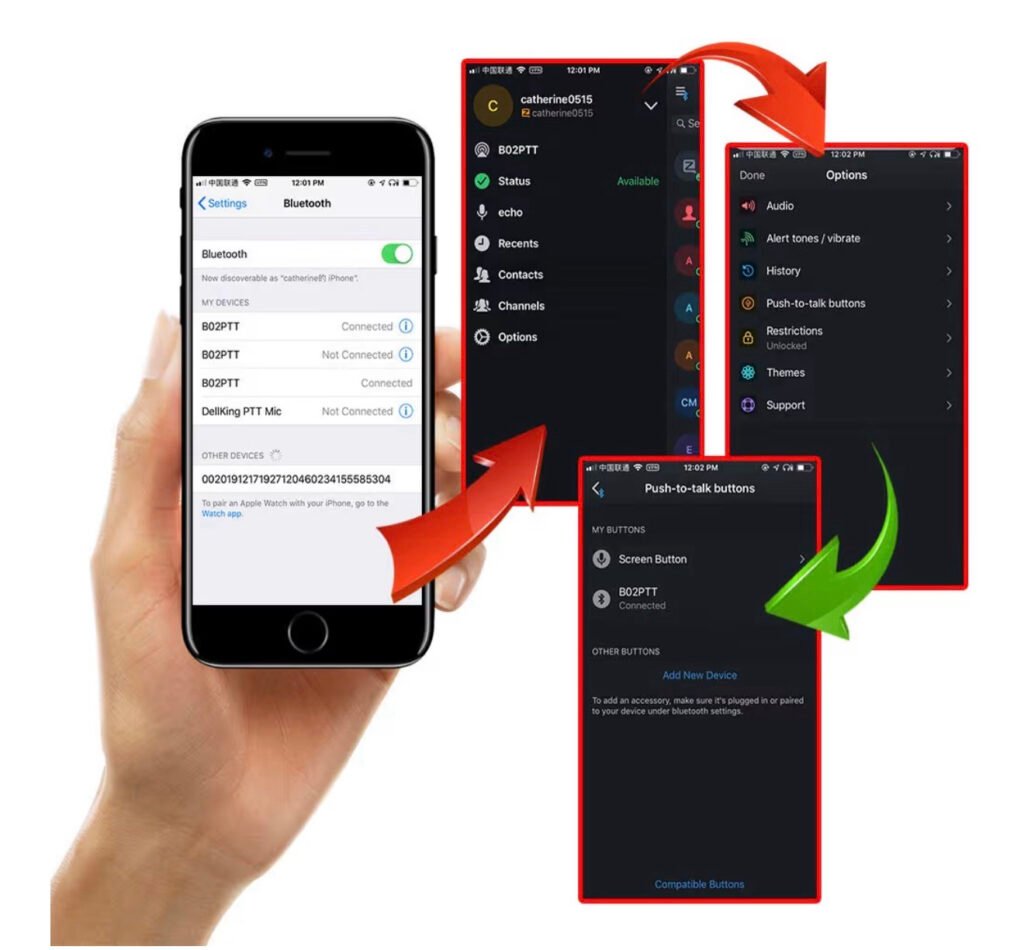
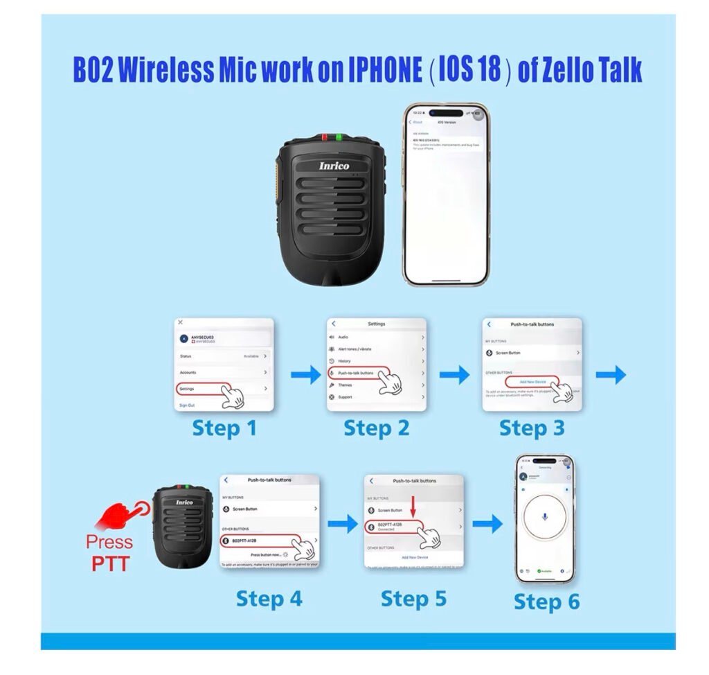
It’s an Inrico B-01 Bluetooth (wireless) Speaker-mic. B-01 is for Android phones, B-02 is for iOS Apple. It cost ~$57, not a bad price for this handy piece of Amateur gear. 1st ‘pair’ the unit with your phone, then activate your EchoLink app, then its Menu: select BlueTooth, then go to the PTT section & select External PTT. I did have to make another minor selection there/can vary, then cycle it’s power. The EchoLink receive audio comes out of this speaker, there’s Volume +/- buttons on the side. The PTT side switch works EchoLink just like a regular mic & sends your voice to EchoLink/beyond This is very handy when we can’t hold our phones while driving/etc but can hold/clip-on this rugged two-way radio mic. It also can be used as a BT speaker again, but now while watching a video/music! Link for more info:
If you’ve been in the ham radio world lately, you’ve heard the buzz: Parks on the Air (POTA) is exploding in popularity — and for good reason!
🗺️ WHAT IS POTA? Parks on the Air is a volunteer-run program that encourages ham radio operators to set up and operate portable stations from designated parks, forests, wildlife refuges, and other public lands. You activate a park by making at least 10 contacts while operating from that location. Hunters — those making contact with activators — log the exchange from home.
📈 WHY IS IT MORE POPULAR THAN EVER?
✅ It gets hams OUTSIDE — combining two great hobbies: radio and the outdoors ✅ It’s beginner-friendly — you don’t need expensive gear to participate ✅ It builds real operating skills — portable setup, antenna experimentation, battery power ✅ There are THOUSANDS of parks to activate across all 50 states and 40+ countries ✅ The community is incredibly welcoming and supportive ✅ Digital logging via the POTA.app makes it easy to track activations and awards ✅ It gives every QSO a purpose — you’re not just calling CQ into the void!
🏅 AWARDS & ACHIEVEMENTS Both activators AND hunters can earn awards, certificates, and recognition — giving you goals to chase whether you’re portable in the field or comfortably at home.
📡 HOW DO YOU GET STARTED? 1️⃣ Visit pota.app and create a free account 2️⃣ Find parks near you using the interactive map 3️⃣ Check spots on the POTA website or DX clusters to hunt activators 4️⃣ Grab a portable rig, a wire antenna, and head outside!
POTA is proof that ham radio is alive, thriving, and growing — one park at a time. 🎉
Frequency is one of the most important concepts in the universe and to antenna theory, which we will see. But fortunately, it isn’t too complicated.
Beginner Level (or preliminaries):
Antennas function by transmitting or receiving electromagnetic (EM) waves. Examples of these electromagnetic waves include the light from the sun and the waves received by your cell phone or radio. Your eyes are basically “receiving antennas” that pick up electromagnetic waves that are of a particular frequency. The colors that you see (red, green, blue) are each waves of different frequencies that your eyes can detect.
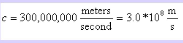
All electromagnetic waves propagate at the same speed in air or in space. This speed (the speed of light) is roughly 671 million miles per hour (1 billion kilometers per hour). This is roughly a million times faster than the speed of sound (which is about 761 miles per hour at sea level). The speed of light will be denoted as c in the equations that follow. We like to use “SI” units in science (length measured in meters,time in seconds,mass in kilograms), so we will forever remember that
Before defining frequency, we must define what a “electromagnetic wave” is. This is an electric fieldthat travels away from some source (an antenna, the sun, a radio tower, whatever). A traveling electric field has an associated magnetic field with it, and the two make up an electromagnetic wave.
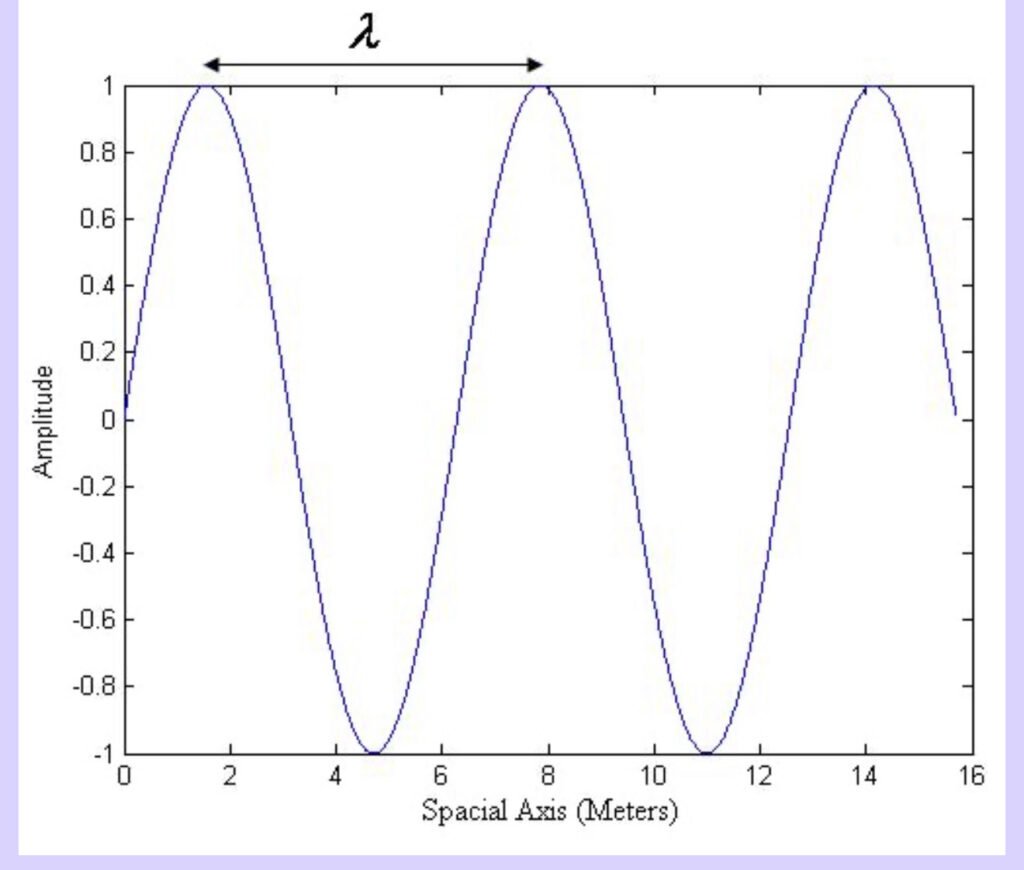
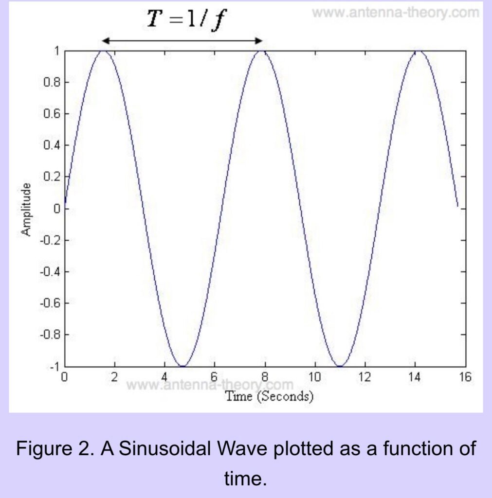
The universe allows these waves to take any shape. The most important shape though is the sinusoidal wave, which is plotted in Figure 1. EM waves vary with space (position) and time. The spatial variation is given in Figure 1, and the the temporal (time) variation is given in Figure 2.
Figure 1. A Sinusoidal Wave plotted as a function of position
The wave is periodic, it repeats itself every T seconds. Plotted as a function in space, it repeats itself every
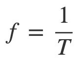
meters, which we will call the wavelength. The frequency (written f ) is simply the number of complete cycles the wave completes (viewed as a function of time) in one second (two hundred cycles per second is written 200 Hz, or 200 “Hertz”). Mathematically this is written as:
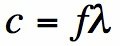
How fast someone walks depends on the size of the steps they take (the wavelength) multipled by the rate at which they take steps (the frequency). The speed that the waves travel is how fast the waves are oscillating in time (f ) multiplied by the size of the step the waves are taken per period (
). The equation that relates frequency, wavelength and the speed of light can be tattooed on your forehead:
Basically, the frequency is just a measure of how fast the wave is oscillating. And since all EM waves travel at the same speed, the faster it oscillates the shorter the wavelength. And a longer wavelength implies a slower frequency.
Why is frequency so fundamental? To really understand that, we must introduce one of the coolest mathematical ideas ever (seriously), and that is ‘Fourier Analysis’. I had a class on Fourier Analysis in grad school at Stanford University, and the professor referred to these concepts as ‘one of the fundamental secrets of the universe’.
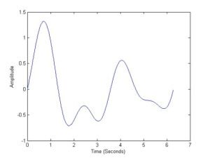
Let’s start with a question. What is the frequency of the following waveform?
Figure 1. A simple waveform.
All waveforms, no matter what you scribble or observe in the universe, are actually just the sum of simple sinusoids of different frequencies
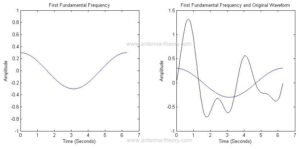
As an example, lets break down the waveform in Figure 1 into its ‘building blocks’ or the it’s frequencies. This decomposition can be done with a Fourier transform (or Fourier series for periodic waveforms).
The first component is a sinusoidal wave with period T=6.28 (2*pi) and amplitude 0.3, as shown in Figure 2.
Figure 2. First fundamental frequency (left) and original waveform (right) compared.
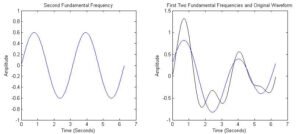
The second frequency will have a period half as long as the first (twice the frequency). The second component is shown on the left in Figure 3, along with the sum of the first two frequencies compared to the original waveform.
Figure 3. Second fundamental frequency (left) and original waveform compared with the first two frequency components.
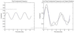
We see that the sum of the first two frequencies is starting to look like the original waveform. The third frequency component is 3 times the frequency as the first. The sum of the first 3 components are shown in Figure 4.
Figure 4. Third fundamental frequency (left) and original waveform compared with the first three frequency components.
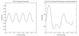
Finally, adding in the fourth frequency component, we get the original waveform, shown in Figure 5.
Figure 5. Fourth fundamental frequency (left) and original waveform compared with the first four frequency components (overlapped).
While this seems made up, it is true for all waveforms. This goes for TV signals, cell phone signals, the sound waves that travel when you speak. In general, waveforms are not made up of a discrete number of frequencies, but rather a continuous range of frequencies.
Hence, for all of antenna theory, we will be discussing wavelength or frequency as a key parameter. Actual antennas radiate real world signals – data from the internet over WIFI, speech signals, etc etc etc. However, since every piece of information in the universe can be decomposed into sine and cosine components of varying frequencies, we always discuss antennas in terms of the wavelength it operates at or the frequency we are using.
As a further consequence of this, the power an antenna can transmit is divided into frequency regions, or frequency bands. In the next section, we’ll look at what we can say about these frequency bands.
How can your cell phone and your television work at the same time? Both use antennas to receive information from electromagnetic waves, so why isn’t there a problem?
The answer goes back to the fundamental secret of the universe. No matter what information you want to send, that waveform can be represented as the sum of a range of frequencies. By the use of modulation (which in a nutshell shifts the frequency range of the waveform to be sent to a higher frequency band), the waveforms can be relocated to separate frequency bands.
As an example, cell phones that use the PCS (Personal Communications Service) band have their signals shifted to 1850-1900 MHz. Television is broadcast primarily at 54-216 MHz. FM radio operates between 87.5-108 MHz.
The set of all frequencies is referred to as “the spectrum”. Cell phone companies have to pay big money to get access to part of the spectrum. For instance, AT&T has to bid on a slice of the spectrum with the FCC, for the “right” to transmit information within that band. The transmission of EM energy is greatly regulated. When AT&T is sold a slice of the spectrum, they can not transmit energy at any other band (technically, the amount transmitted must be below some threshold in adjacent bands).
The Bandwidth of a signal is the difference between the signals high and low frequencies. For instance, a signal transmitting between 40 and 50 MHz has a bandwidth of 10 MHz. This means that the energy of the signal is contained between 40 and 50 MHz (and the energy in any other frequency range is negligible).
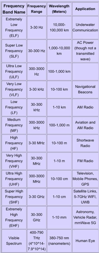
We’ll wrap up with a table of frequency bands along with the corresponding wavelengths. From the table, we see that VHF is in the range 30-300 MHz (30 Million-300 Million cycles per second). At the very least then, if someone says they need a “VHF antenna”, you should now understand that the antenna should transmit or receive electromagnetic waves that have a frequency of 30-300 MHz.
Basically the frequency bands each range over from the lowest frequency to 10 times the lowest frequency. Antenna engineers further divide the bands into things like “X-band” and “Ku-band”
Skip the travel and take your Amateur Radio exam from the comfort of your own home! Our team of friendly Volunteer Examiners (VEs) is here to help you join the airwaves or level up your current license in a professional, stress-free virtual environment.
• When: Flexible 24/7 scheduling to fit your life.
• Where: Fully online via Zoom.
• Process: Guided by our experienced N9BI examiners.
Preparation Checklist:
• A computer equipped with a webcam and mic.
• A stable internet connection and a private, quiet space.
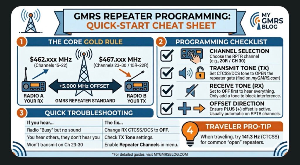
This guide covers the universal logic used by most GMRS-certified radios (like those from BTECH, Wouxun, Midland, and Radioddity). Use this to ensure your radio is talking to the repeater correctly every time.
1. The Core “Golden Rule”
GMRS repeaters operate on a \bm{+5.000\text{ MHz}} Offset.
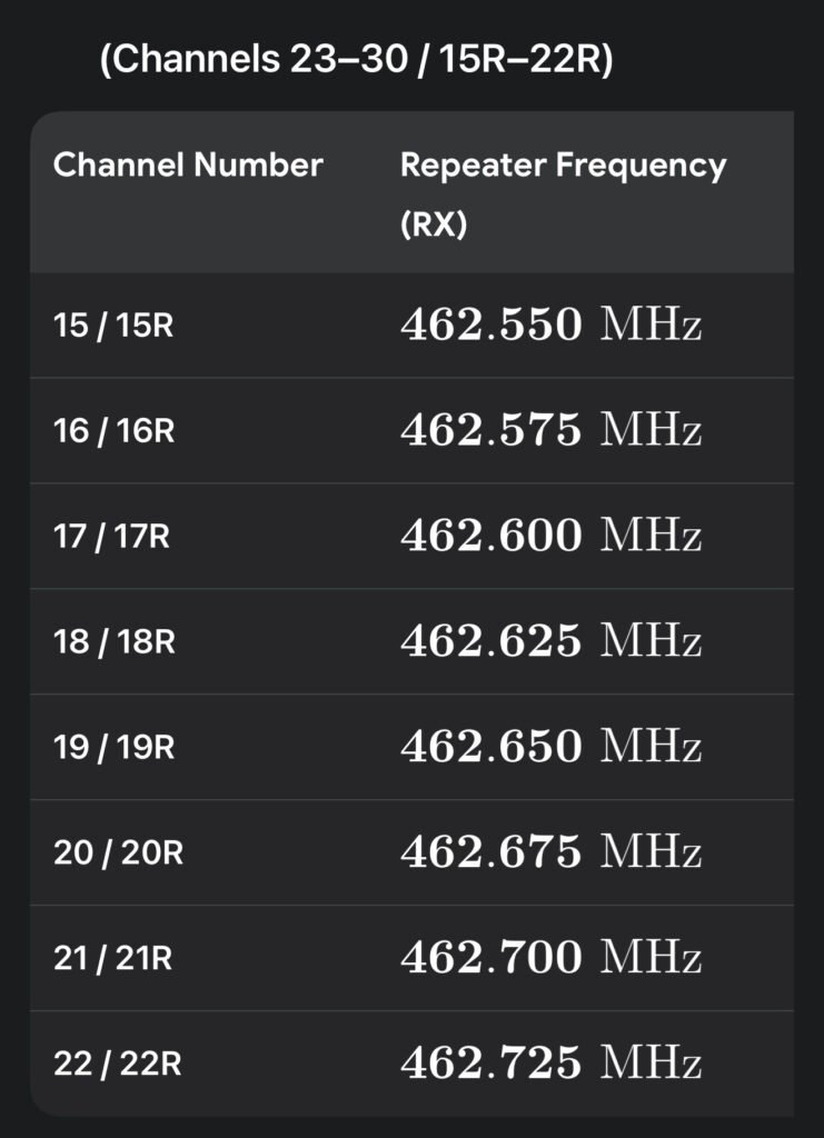
• You Listen (RX) on: \bm{462.\text{xxx MHz}} (Channels 15–22)
• You Talk (TX) on: \bm{467.\text{xxx MHz}} (Channels 23–30 / 15R–22R)
2. Programming Checklist
Check off these four settings in your radio’s menu to ensure a successful connection:
• [ ] Channel Selection: Choose the repeater-specific channel (e.g., 20R or CH 30).
• [ ] Transmit Tone (TX CTCSS/DCS): Set this to the tone required by the repeater owner (found on myGMRS.com). This “opens” the repeater’s gate.
• [ ] Receive Tone (RX CTCSS/DCS): Set this to OFF or None first. Only add a tone here if you want to block out other interference.
• [ ] Offset Direction: Ensure it is set to PLUS (+). Most GMRS radios do this automatically on repeater channels.
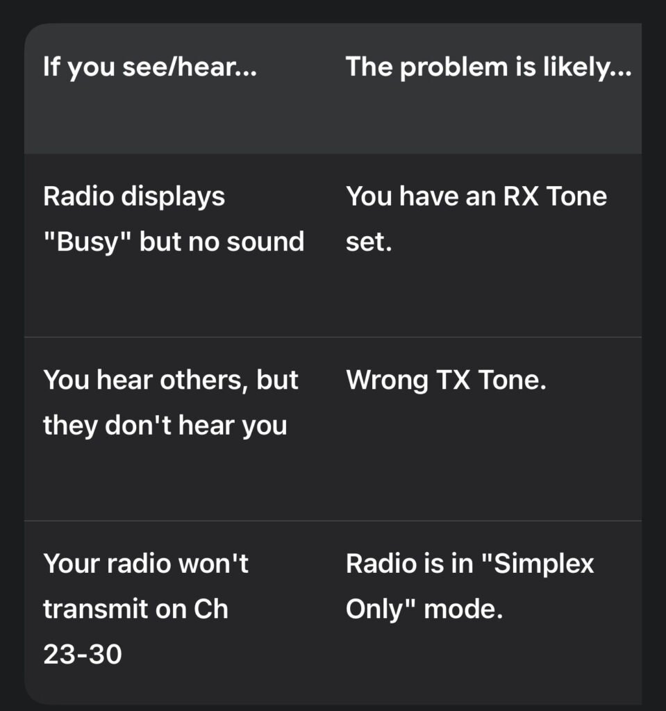
3. Troubleshooting: Why Can’t I Hear the Repeater?
Pro-Tip: If you are traveling and don’t know the local tone, try 141.3 Hz. This is the widely accepted “traveler’s tone” used by many open repeaters across the country.
4. Sample Radio Check
“This is [Your Call Sign], listening on the [Repeater Name] repeater. Can I get a signal report?”
Wait for a response. If you hear a short burst of static (the “tail”) after you let go of the PTT, you have successfully “hit” the repeater!
Whether you’re a traveler crossing state lines or a homeowner looking to bolster your family’s emergency preparedness, GMRS (General Mobile Radio Service) is one of the most practical tools in your kit. While handheld-to-handheld (simplex) range is fine for a hike, repeaters are what truly unlock the potential of the service, turning a 2-mile radio into a 50-mile lifeline.
What is a GMRS Repeater?
In simple terms, a repeater is a powerful radio station located on a high point—like a hilltop, a tower, or a tall building. It “listens” for your signal on one frequency and simultaneously “retransmits” it on another at much higher power.
• Simplex: Radio A talks directly to Radio B. (Range: 1–5 miles)
• Repeater: Radio A talks to the Repeater, which then blasts that signal out to Radio B. (Range: 20–50+ miles)
The Traveler’s Advantage
If you are on the road, GMRS repeaters provide a level of security that cell phones can’t match in “dead zones.”
• Finding Repeaters: Before you head out, check resources like myGMRS.com. It’s the gold standard for GMRS directories. You can see maps of active repeaters along your route and find out if they are “Open” or “Permission Required.”
• The Travel Tone: Many repeaters intended for traveler assistance use a standard 141.3 Hz CTCSS tone. It’s a good idea to program your “traveler” channels with this tone as a starting point.
• Scanning: If you’re in a new area and don’t have the data, set your radio to scan the 8 repeater channels (15–22) with “Carrier Squelch” (no tones) to see where the local activity is.
Home & Emergency Use
For the home user, a repeater acts as a “community hub.” During a power outage or when cell towers are overwhelmed, a local repeater allows neighbors and family members to stay coordinated.
• Family Coverage: One GMRS license covers your entire immediate family. This makes it incredibly cost-effective to get everyone a radio and teach them how to hit the local repeater.
• Base Stations: Using a 15W to 50W mobile radio as a base station with an external antenna on your roof will significantly improve your ability to reach distant repeaters compared to a small handheld.
Repeater Etiquette: The Unwritten Rules
Since most repeaters are privately owned and maintained by enthusiasts, following the rules keeps the community healthy:
1. Identify Yourself: FCC rules require you to state your call sign every 15 minutes and at the end of your conversation.
2. Listen First: Before you key up, listen for a few seconds to make sure you aren’t interrupting an ongoing conversation.
3. The “Pause”: After you press the Push-to-Talk (PTT) button, wait about one second before speaking. Repeaters often have a slight delay in “waking up,” and this prevents your first few words from being cut off.
4. No Roger Beeps: Most repeater owners find the “beep” at the end of a transmission annoying and unnecessary. It’s best to turn it off in your settings.
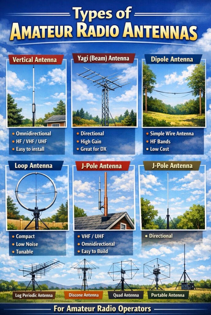
Here are some of the most common amateur (ham) radio antenna types you’ll encounter. Since you already have a pretty advanced antenna setup at your house (flagpole mast with HF and VHF/UHF antennas), this will help visualize the broader landscape of antenna designs.
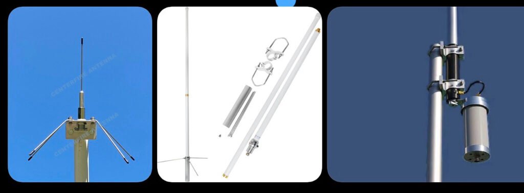
Vertical Antenna
Description
Mounted vertically and radiates equally in all directions (omnidirectional). Common for HF, VHF, and UHF base stations. Often fiberglass with internal wire elements.
Pros
Simple installation Good for general coverage Small footprint
Cons
Typically lower gain than directional antennas.
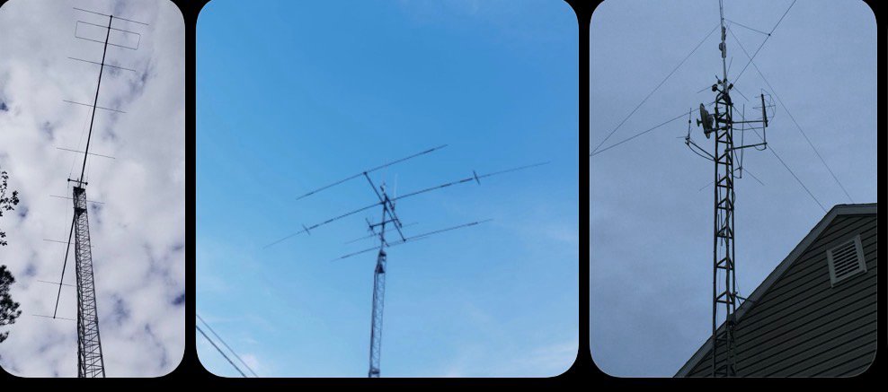
Yagi (Beam) Antenna
Description
Directional antenna with multiple elements. Focuses signal in one direction for long-distance communication.
Pros
High gain Excellent for DX contacts Reduces interference from other directions
Cons
Large and requires a rotor More expensive and complex.
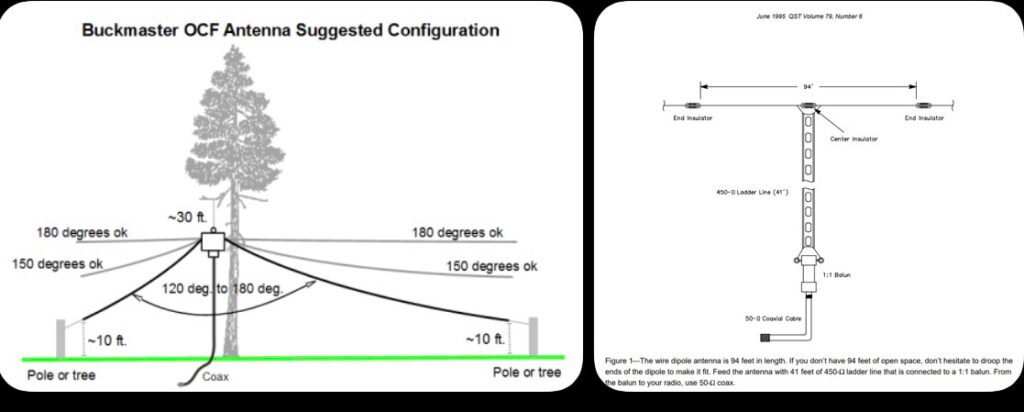
Dipole Antenna
Description
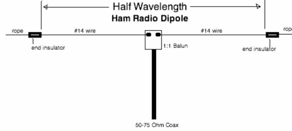
One of the simplest and most effective HF antennas. Two wire elements fed from the center.
Pros
Cheap and easy to build Very efficient Great for HF bands
Cons
Requires space between two supports.
Loop Antenna
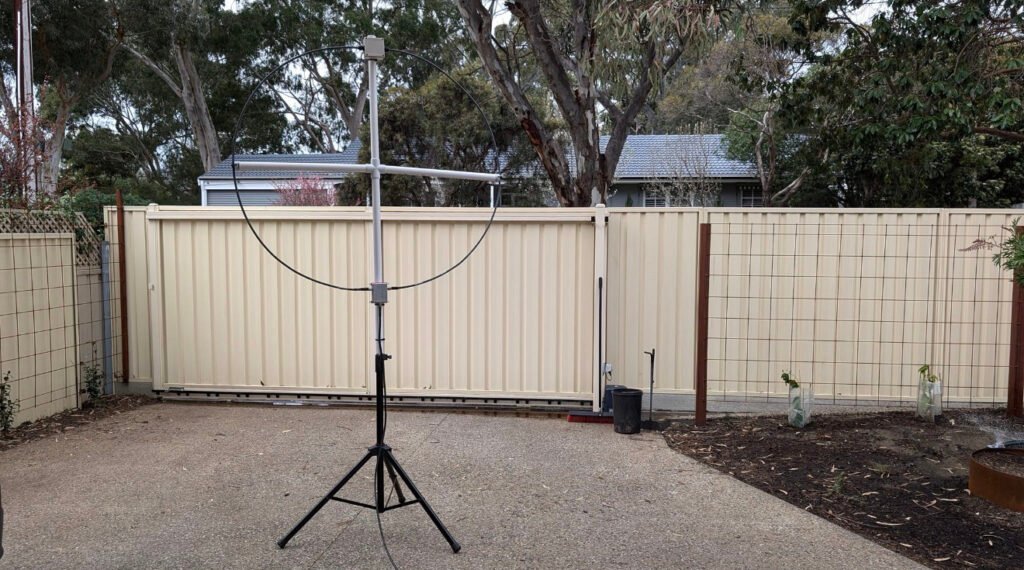
Description
Circular or square loop used for HF operation. Often used in limited space environments.
Pros
Compact Very quiet receive characteristics Works well in apartments
Cons
Narrow bandwidth Requires tuning.
J-Pole Antenna
Description
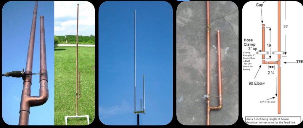
Very common VHF/UHF antenna design. Essentially a half-wave radiator fed by a quarter-wave matching stub.
Pros
Simple design Omnidirectional Great for repeaters and local communication
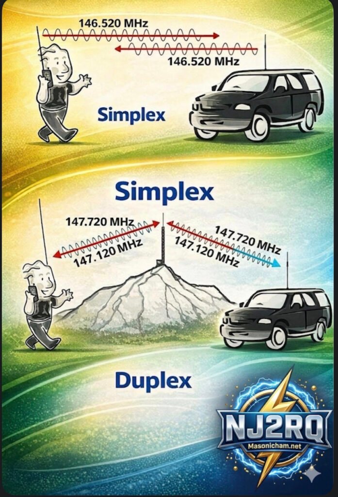
Have you ever key-ed up your handheld radio, ready to ask a friend across town how their day is, and then paused, paralyzed by the cryptic instructions on your radio’s screen or the unfamiliar terms you hear on the air? The world of amateur radio, or “ham” radio, is full of exciting possibilities, but it can also be a maze of technical jargon. Fear not, fellow operator! Today, we’re pulling back the curtain on one of the most fundamental concepts in our hobby: Simplex versus Duplex, or the fascinating world of repeaters.
Take a look at this detailed infographic we’ve put together. It’s designed to make these core concepts crystal clear, but sometimes a visual guide is even better with a companion explanation. Let’s break it down, section by section, starting with the simplest form of communication.
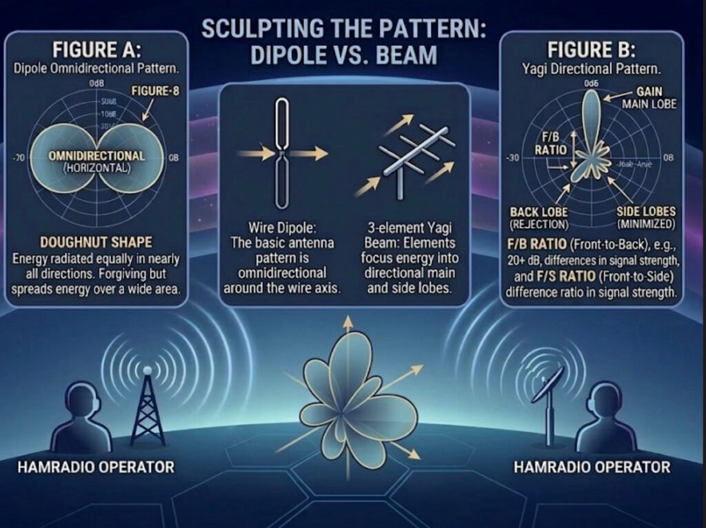
Figure A: The Simplex – When Simple is Best
Think of the Simplex pattern, shown on the far left of the diagram, as a focused flashlight beam in the pitch-black night. It’s direct, straightforward, and covers a wide area for local communication.
Here, we’re comparing it specifically to a simple dipole antenna—the oldest and most common type of antenna in the ham radio world. The pattern itself, that large “Figure-8” you see in Figure A, is a 2D slice of how the energy radiates from that horizontal wire. It’s called an “Omnidirectional (Horizontal)” pattern, often described as a “Doughnut Shape.”
What does this mean for you as an operator?
This pattern is excellent for broad, local communication because your energy is radiated almost equally in every direction away from the axis of the antenna. You don’t need a massive, rotating antenna tower or a highly-tuned beam to make successful local contacts on the 2m or 70cm bands. This is also the fundamental behavior of every dipole antenna, making it the bedrock of antenna design. But as the text notes, because it’s so “forgiving” and spreads that energy out over a vast 360-degree area, your signal becomes relatively weak by the time it reaches a very distant receiver. To reach over greater distances with less power, we need to get more directional.
Sculpting the Pattern: Dipole VS. Beam
The central panel shows the transition. We can take that basic, spread-out dipole pattern and “sculpt” it by adding a few carefully calculated passive elements. This creates the pattern on the right: a highly-focused directional beam, which acts more like a high-intensity laser than a broad flashlight.
As illustrated, adding a simple reflector element behind the original dipole element (which is now the “driven element”) and perhaps a few smaller director elements in front of it will dramatically change how the energy behaves. The 3-element Yagi beam on the right, for example, is a classic design that achieves this transformation. You focus and redirect that otherwise wasted energy from the back and sides, concentrating it all into one powerful lobe of gain.
Figure B: The Yagi Beam – Focus and Gain for the Real-World Advantage
This brings us to the most complex and exciting part of the chart: Figure B, the Yagi Directional Pattern. Here, that same energy is now shaped into a main, powerful lobe pointing directly at your target. But that focus comes with complexity, creating several distinct lobes that every operator should understand:
• MAIN LOBE: This is your best friend. It is the peak concentration of all your focused power. When propaganda conditions are tough, this is the lobe that can punch your signal through to that rare DX contact.
• GAIN: This is the practical advantage that all this focus buys you. It’s measured in decibels (dB) and essentially represents how much “louder” you appear to the other station compared to that reference dipole we started with. More gain is almost always better for overcoming noise or distance.
• BACK LOBE (REJECTION): The mirror image of the main lobe, but often much smaller. Good antenna designs minimize this to prevent picking up unwanted noise or interfering signals from the wrong direction. The goal is to maximize “REJECTION,” making your antenna blind to signals from behind.
• SIDE LOBES (MINIMIZED): These are like secondary beams that point in unwanted directions. Just like back lobes, a high-quality antenna will minimize these to optimize efficiency.
• F/B RATIO (Front-to-Back): This is a critical measurement. A ratio like 20+ dB, as noted, means your main signal is 20 dB (or 100 times!) stronger than the signal coming in from the exact opposite direction. This is the difference between a clear, one-on-one contact and a chaotic interference fest.
• F/S RATIO (Front-to-Side): Similar to the F/B ratio, but measured against the side lobes. It tells you how effective the antenna is at filtering out noise and other stations that are off-axis to your main direction. A high F/S ratio makes for a quieter, more focused receiver.
The Real-World Connection: Hamradio Operator QTH A to QTH B
Finally, the bottom of the infographic puts these abstract concepts into a real-world scenario. Two operators, HAMRADIO OPERATOR (QTH A) and HAMRADIO OPERATOR (QTH B), are trying to connect over a challenging distance.
When the propagation is tricky (maybe the solar flux is low), simply pointing their high-gain Yagi beams at each other (the “Doughnut Shape” versus the “laser focus”) can make all the difference. Their 3D multi-petal beam visualization illustrates how they are sculpting the ideal propagation path with focused energy to maximize their odds of a successful contact. It’s not just about raw power; it’s about smart, efficient design.
The Bottom Line:
An infographic like this is a powerful visual reminder that as ham radio operators, we’re not just users of technology—we’re engineers of our own signals. By understanding these concepts and using the right tools, whether it’s the simplicity of a dipole or the surgical precision of a high-gain beam, you can make smarter decisions, overcome limitations, and truly unlock the potential of your radio setup.
What kind of antenna patterns are you using at your station? Share your experiences in the comments below, and let’s keep the discussion focused and forward-looking.
In our last post, we explored how the ionosphere is a moving, shimmering curtain that creates signal fluctuations like QSB and Fading. But understanding propagation is only half the battle. To effectively communicate on the HF bands, you also need to understand your Antenna Radiation Pattern. This pattern is essentially a blueprint of where your antenna sends (or receives) energy.
Let’s look at this comparison diagram to visualize why a dipole in your backyard behaves so differently from a large multi-element Yagi beam.
The Power of Focus: Omindirectional vs. Directional
An antenna’s pattern is a 3D plot of its relative field strength. This diagram simplifies it into a horizontal 2D slice, which is perfect for understanding directional gain.
1. The Omnidirectional “Doughnut” (Figure A – Dipole)
The pattern on the left is typical of a horizontally oriented dipole antenna.
• What it means: Energy is radiated broadly in nearly all directions. It is “omnidirectional” in the horizontal plane (forming a doughnut shape around the wire).
• The Takeaway: This is excellent for general operating and making contacts without needing to rotate your antenna. It’s forgiving, but it spreads your energy thin over a vast area.
2. The Directional “Flashlight” (Figure B – Beam)
The pattern on the right shows a high-gain directional antenna, like a Yagi or quad loop array. Notice how the energy isn’t just a circle; it’s sculpted into distinct lobes.
• The Main Lobe: This is where the majority of your energy is focused. It acts like a powerful flashlight beam, concentrating power in one specific direction.
• The Back and Side Lobes: This is “wasted” or secondary energy radiating in directions you aren’t trying to target. High-quality antenna designs minimize these to maximize the main lobe.
• The Gain Effect: By focusing your 100 watts into that narrow main lobe instead of a big omnidirectional doughnut, your signal “appears” many times stronger at the distant receiving station. This is called antenna gain.
3. Front-to-Back (F/B) and Front-to-Side (F/S) Ratios
A key specification for any directional antenna is how well it rejects signals from the sides and back.
• F/B Ratio: This is the difference in signal strength between the peak of the Main Lobe (front) and the peak of the Back Lobe. A high ratio (e.g., 20+ dB) means that weak stations behind you will be much quieter, helping you focus on the station you are aiming for.
• F/S Ratio: Similarly, this is the difference between the main lobe and the Side Lobes. It tells you how effective the antenna is at “ignoring” noise or interference from directions other than your primary target.
Your Signal is a Laser, Not a Floodlight
Thinking about your antenna pattern is crucial. When propagation is challenging, a few extra dB of focused gain from a directional antenna can be the difference between a successful QSO and vanishing into the noise.
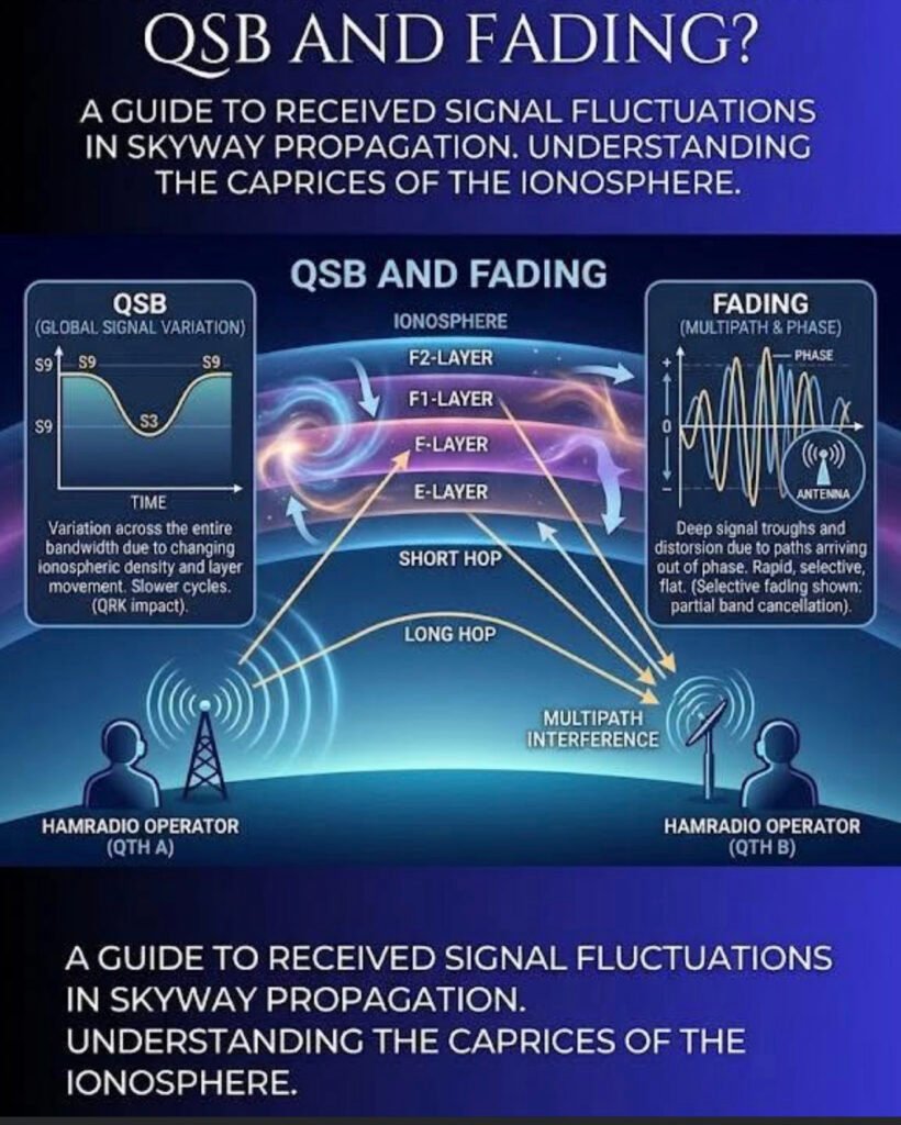
If you’ve spent any time on the high-frequency (HF) bands, you know the ionosphere is far from a stable mirror. It’s more like a moving, shimmering curtain. This graphic perfectly illustrates the two main ways that “shimmer” affects your signal: Global Signal Variation (QSB) and Multipath Interference (Fading).
1. QSB: The Slow Roller
In the left panel, we see QSB (a Q-code used to describe signal strength variation).
• What it is: A global change in signal intensity across your entire bandwidth.
• The Cause: As the sun’s radiation fluctuates or the density of the ionospheric layers (E, F1, F2) shifts, the “reflectivity” of the sky changes.
• The Effect: You’ll notice your S-meter moving from an S9 down to an S3 and back again over a period of seconds or even minutes. It’s a slow, rhythmic cycle that affects the whole signal equally.
2. The Ionospheric Layers: The “Bounce” House
The center of the image shows the Short Hop and Long Hop propagation.
• F2-Layer: Usually the highest and most important for long-distance (DX) communication.
• E-Layer: Lower down, often responsible for “Short Skip” or Sporadic-E openings.
The signal doesn’t just hit one spot; it can take multiple paths to reach the receiving station (QTH B).
3. Fading: The Phase Killer
The right panel highlights Fading, which is often much more “violent” and rapid than standard QSB.
• The Cause (Multipath Interference): Your signal travels via different paths—one might bounce off the F2 layer while another bounces off the E layer. Because these paths are different lengths, the signals arrive at the receiving antenna at slightly different times.
• The Result: When these signals meet, they can be out of phase. If the peak of one wave hits the trough of another, they cancel each other out.
• The Sound: This results in “selective fading,” where the audio might sound hollow, distorted, or watery. It’s not just getting quieter; the signal itself is being mangled in real-time.
The Takeaway for Operators
When you hear a signal “pumping” or distorting, you’re hearing the literal movement of the atmosphere miles above the Earth. While we can’t change the ionosphere, understanding these fluctuations helps us better time our transmissions and adjust our expectations for that rare DX contact.
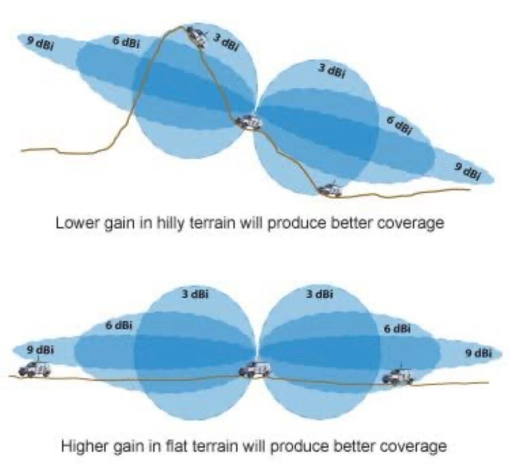
Have you ever wondered why some antennas claim to have “gain” while others don’t? It sounds like magic, but in the ham radio world, it’s actually all about how you focus your energy.
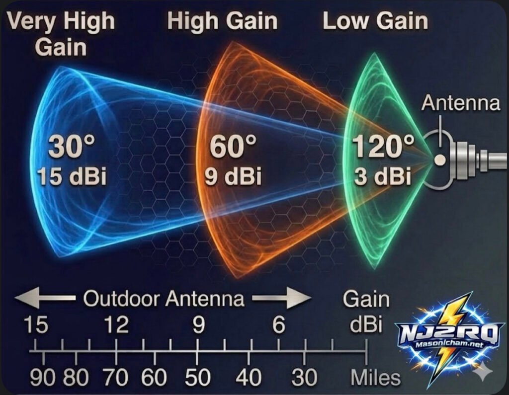
Check out this new card I put together to help visualize how it works:
The Big Secret: It’s Not an Amplifier!
Here is the most important thing to remember: with any antenna, the apparent increase in signal is not actually an amplification of the signal. Antennas are passive, meaning they don’t have a power plug to create more energy.
Instead, gain is simply the act of redistributing the available Radio Frequency (RF) signal into a preferred direction. Think of it like a flashlight: the bulb stays the same brightness, but the reflector concentrates all that light into a tight beam so you can see much further. Basically, antennas only divert, direct, or concentrate radio energy; they don’t create it.
Understanding the Trade-off
As you can see on the card, there is always a “give and take”:
Low Gain (3 dBi): You get a very wide coverage area (120°), but your signal doesn’t travel as many miles. Great for local ragchews!
High Gain (9 dBi): The beam narrows down to 60°. You lose some side coverage, but you gain a lot of distance—reaching out to about 50 miles in this example.
Very High Gain (15 dBi): This is a “laser beam” at 30°. It’s perfect for DXing (long-distance) because it concentrates your signal to reach 90 miles or more, but you have to point it exactly at the other station!
Pro Tip for the Shack: When you see a gain rating in dBi, it’s comparing the antenna to an “Isotropic” source (an imaginary point that radiates equally in every single direction like a perfect sphere). When you’re picking a Yagi or a directional wire antenna, remember that a higher gain number means you’re “squeezing” your signal into a tighter spot to reach further away!
What’s your go-to antenna for reaching those far-off DX stations? Do you prefer a wide “floodlight” or a narrow “spotlight”? Let me know in the comments!
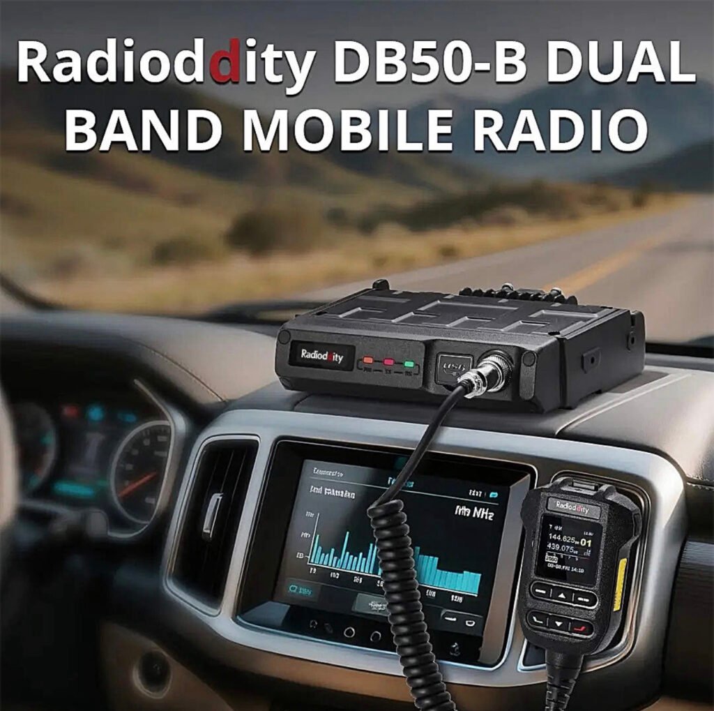
This mobile radio is a major step up for anyone tired of clunky menus and tethering themselves to a laptop just to program a few repeaters. The Radioddity DB50-B isn’t just another 50W mobile; it’s a smartphone-integrated powerhouse that changes how you interact with your gear.
If you’ve been in the ham hobby for more than five minutes, you know the “Mobile Radio Struggle.” You spend an hour mounting a radio in your truck, only to realize you need a proprietary cable and a Windows 10 laptop just to change a PL tone.
The Radioddity DB50-B just ended that era.
I’ve been putting this unit through its paces, and it’s clear: the “B” stands for “Bluetooth,” and it’s a total game-changer. Here’s why this radio needs to be in your shack (or your dashboard) right now.
1. No More Cables. Ever.
The headline feature is the app-based programming. You can configure channels, update settings, and even push firmware updates (OTA) directly from your smartphone via Bluetooth. Whether you’re on the trail or in the driveway, you can fix your programming in seconds without touching a PC.
2. APRS & KISS TNC Built-In
For the digital junkies and emergency prep crowd, this is huge. It has a built-in GPS and a Bluetooth KISS TNC. This means you can run APRS or even Winlink (using apps like RadioMail) directly through the radio. It turns your smartphone into a powerful digital terminal with zero extra hardware.
3. Serious Power, Small Footprint
Don’t let the compact size fool you. This is a true 50W powerhouse on both VHF and UHF.
• Dual Band / Dual Watch: Monitor two frequencies at once.
• AI Noise Reduction: The intelligent noise suppression actually works. It filters out wind and road noise, making your audio punch through even if you’re driving with the windows down.
• Airband Reception: Want to listen to local aviation? It’s built right in.
4. The “Microphone is the Radio” Design
The front panel is minimalist because the real control happens at the microphone and the app. The mic is ergonomic, easy to read, and puts every function at your fingertips. If you’re tight on space in a modern vehicle, this is the cleanest install you’ll ever find.
The Verdict: Should You Buy It?
If you want a radio that feels like it was built in 2025 rather than 1995, the answer is yes. It’s powerful, it’s digital-ready, and the smartphone integration makes every other mobile radio feel like a dinosaur.
If you’ve been exploring the world of digital amateur radio, you’ve probably heard about expensive handhelds packed with features that cost hundreds of dollars. But what if there was a radio that delivered modern digital capability, impressive performance, and incredible value all in one package?
Meet the Radioddity GD-168 — a handheld that is quietly becoming a favorite among operators who want powerful digital communication without breaking the bank.
And once you see what this radio can do, it’s easy to understand why.
A Radio Built for the Modern Ham
The GD-168 isn’t just another handheld—it’s designed for the modern amateur radio operator who wants flexibility.
With dual-band VHF/UHF capability, the radio works beautifully on both analog repeaters and digital DMR networks. That means you can check into your local net one minute and connect to operators across the globe the next.
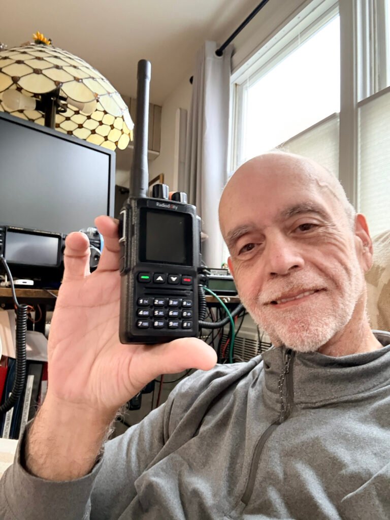
Whether you’re using a repeater or connecting through a hotspot like the SharkRF openSPOT4 Pro, the GD-168 delivers smooth, reliable communications.
And that’s where things get really exciting.
Talk Around the World From Your Handheld
Digital radio has changed amateur radio forever. Instead of being limited to local repeaters, operators can now connect through global networks and talk to hams around the world.
The GD-168 makes that experience effortless.
With support for DMR digital voice, you can connect to worldwide talkgroups and instantly communicate with operators across continents. One moment you’re chatting locally—next moment you’re talking with someone in Europe or Australia.
That kind of capability used to require expensive equipment. Now it fits in the palm of your hand.
Modern Features That Make Operating Easy
One of the first things you’ll notice is the bright color display. Channel information, talkgroup data, signal strength, and battery status are all presented clearly and cleanly.
But the real magic is under the hood.
The GD-168 includes:
• Dual-band VHF/UHF operation
• Analog and DMR digital modes
• USB-C charging and programming
• Large contact database capacity
• Clear, powerful audio output
Radioddity even includes two batteries and two antennas in the box, making the radio ready to go right out of the package.
Audio That Stands Out
A radio can have all the features in the world, but if the audio isn’t good, it doesn’t matter.
Thankfully, the GD-168 delivers clear and loud audio quality that makes conversations easy to understand—even in noisy environments.
Whether you’re operating from your shack, the car, or a portable setup, the radio provides strong, reliable communications.
Incredible Value
One of the biggest surprises about the GD-168 is the price. Radios with similar capabilities often cost far more.
Yet this radio delivers:
• Digital voice capability
• Dual-band operation
• Modern charging via USB-C
• Excellent audio performance
All in a radio that remains very affordable for most operators.
For new operators exploring DMR or experienced hams wanting a capable secondary radio, the GD-168 represents exceptional value.
Final Thoughts
Amateur radio continues to evolve, and radios like the Radioddity GD-168 are helping bring the hobby into the modern era.
It combines traditional ham radio operation with powerful digital connectivity, opening doors to communication that were unimaginable just a few decades ago.
For many operators, the GD-168 is becoming a favorite handheld for everyday operation, portable setups, and digital exploration.
And once you start using it, it’s easy to see why.
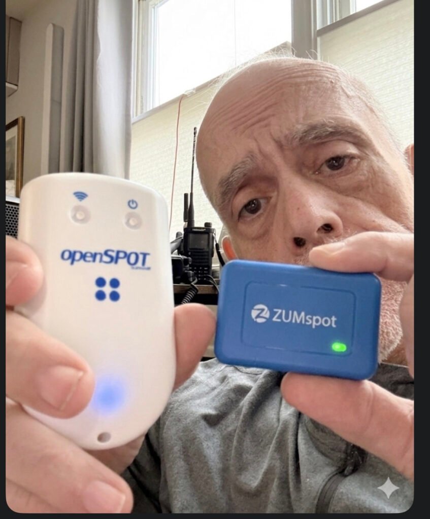
In the world of digital amateur radio, your hotspot is more than just a bridge—it’s the heart of your station. As we navigate the tech landscape of 2026, two names still dominate the conversation. But they couldn’t be more different. One is a sleek, “it just works” masterpiece; the other is the ultimate tinkerer’s toolkit.
If you’re standing at the crossroads of a purchase, it’s time to stop looking at spec sheets and start looking at how you actually want to spend your time in the shack.
The Philosophy of the “Appliance” vs. the “Computer”
The fundamental divide between these two devices isn’t just the price tag—it’s the operating system.
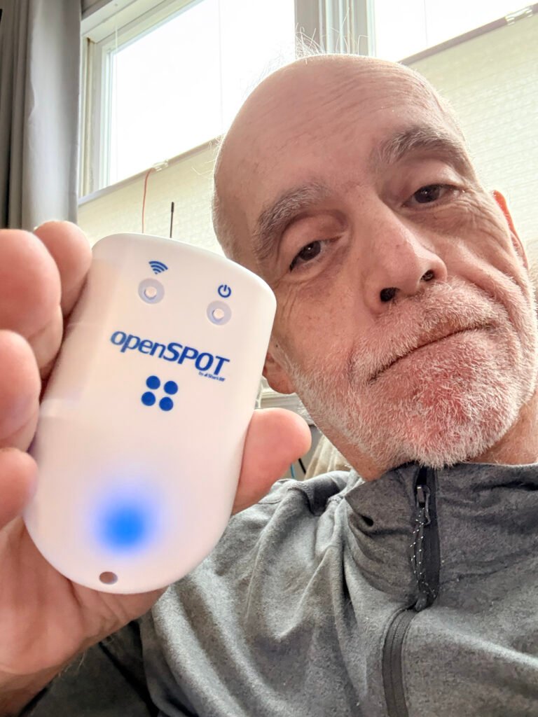
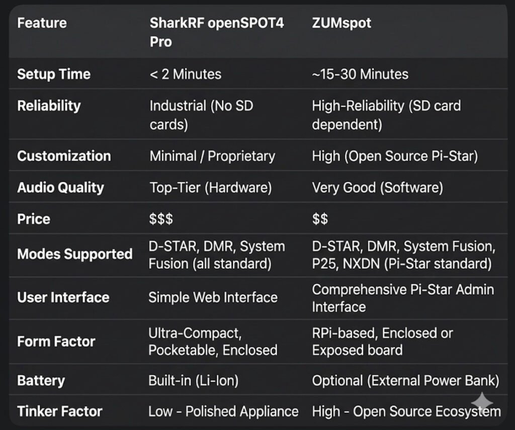
• The SharkRF openSPOT4 Pro runs on a Custom RTOS (Real-Time Operating System). It doesn’t use an SD card. It doesn’t “boot up” like a computer; it wakes up like a toaster. You can yank the power cord mid-transmission, and you will never face a corrupted file. It is built for the operator who wants zero friction.
• The ZUMspot is built on the back of the Raspberry Pi (Linux). It is a full-blown computer in the palm of your hand. While this gives you the power of the Pi-Star or WPSD ecosystems, it comes with the “Linux Tax.” You need a proper shutdown procedure, a high-quality SD card, and the patience to troubleshoot a kernel update every now and then.
Hardware Transcoding: The Pro’s Secret Weapon
This is where the “Pro” in the openSPOT4 Pro earns its keep. It houses a dedicated AMBE+2® hardware chip.
In 2026, cross-moding is the name of the game. If you want to use your favorite DMR handheld to talk on a D-STAR reflector, the SharkRF does the heavy lifting in hardware. The result? Audio that is crisp, clear, and devoid of the “underwater” robotic artifacts often found in software-based transcoding.
The ZUMspot, while incredibly capable, relies on the CPU for these conversions. It’s good—don’t get me wrong—but in a side-by-side “Golden Ear” test, the hardware-baked audio of the SharkRF wins every time.
Portability: The 30-Hour Myth?
SharkRF loves to tout that 30-hour battery life. In the real world, if you’re hitting the PTT frequently and running high RF power, you’re looking at 8 to 12 hours. It’s plenty for a day at the park, but it’s not a week-long expedition.
The ZUMspot has no internal battery, which sounds like a downside—until you realize you can plug it into a standard 20,000mAh USB power bank. That “clunky” setup will keep your ZUMspot humming for 3 to 4 days straight, making it the actual king of long-term emergency portable use.
The “No-Radio” Revolution
One of the most underrated features of the openSPOT4 Pro is SharkRF Link.
“Imagine being at a restaurant or a boring meeting and realizing there’s a massive net happening. You don’t have your radio. No problem.”
With the SharkRF app, your smartphone becomes the radio. It uses your phone’s mic and speaker to bridge directly into the hotspot. The ZUMspot, by design, almost always requires a physical transceiver to get your voice into the digital stream.
The Verdict: Which One Is For You?
Buy the openSPOT4 Pro if:
You want the “iPhone” experience. You travel, you want high-fidelity audio, and you want a device that is ready to talk before you’ve even finished your coffee.
Buy the ZUMspot if:
You want the “Linux” experience. You love the maker movement, you want a massive 3.5-inch color screen on your desk, and you find joy in the “build” as much as the “talk.”
The digital world is waiting. Which bridge are you crossing?
If you’ve been following my radio journey, you know I’m a sucker for gear that balances performance with value. That’s why I am beyond stoked to officially welcome Radioddity to the blog!
Whether you are just studying for your Technician license or you’re a seasoned DXer looking for your next field-op rig, Radioddity has been shaking up the amateur radio world for years. They aren’t just selling radios; they are making the hobby more inclusive by proving you don’t need a thousand-dollar budget to get clear signal reports.
Why I’m Excited:
• Innovation for Everyone: From the legendary (and rugged) handhelds to their sleek new HF rigs, they listen to the ham community.
• Built for the Field: Their gear is famous for being “SOTA-ready”—lightweight, durable, and ready for the trail.
• The “Bang for Buck” Factor: You’re getting modern features (like true dual-band monitoring and color displays) at a fraction of the usual cost.
Bottom line: If you’ve been waiting for a sign to upgrade your handheld or finally dive into digital modes, this is it.
🚀 Ready to see what’s new?
I’ve curated a list of my personal favorites—from the “bulletproof” starters to the high-end mobile units. Trust me, your shack (and your wallet) will thank you.
Welcome to the definitive guide on AllStar Link (ASL). If you are looking for the “Gold Standard” in linking amateur radios across the globe, you’ve found it. At masonicham.net, we don’t just use the tech; we master it.
1. What Exactly is AllStar Link?
AllStar Link is a high-performance network of amateur radio nodes and repeaters linked via the internet. Unlike older systems that can sound scratchy or “robotic,” AllStar uses Voice over IP (VoIP) technology—the same high-fidelity tech used by major phone networks—to transmit your voice.
The “Asterisk” Magic
The secret sauce is a software called Asterisk. Originally built for massive corporate phone systems, a brilliant Ham named Jim Dixon (WB6NIL) adapted it for radio. He created a module called app_rpt that allows a computer to act as a radio controller. This means your radio is no longer just a “walkie-talkie”; it’s a powerful, internet-connected broadcast station.
2. The Hardware: Building Your “All-Star” Station 🛠️
To get started, you need more than just a radio. You need a Node. Think of a Node as your personal gateway to the world. Here is the detailed breakdown of what’s inside:
The Brain: Raspberry Pi
Raspberry Pi 4 or 5: These are the current heavyweights. They have the processing power to handle high-quality audio without “jitter” or lag.
The OS: We use ASL3 (AllStarLink Version 3), built on the stable Debian Linux platform.
The Interface: The “Translator”
The computer (Pi) and the radio speak different languages. You need a USB Radio Interface (URI) to translate:
SHARI (SA818): A popular “All-in-One” USB stick that contains a tiny UHF or VHF radio. Perfect for talking around your house and yard.
External URI: If you want to connect a powerful 50-watt mobile radio or a mountain-top repeater, you use a dedicated URI cable (like those from Masters Communications) to link the Pi to the radio’s “Data” port.
The Radio
Handhelds: Any analog FM radio (Baofeng, Yaesu, Icom, Kenwood) works!
The Beauty of Analog: You don’t need a $600 digital radio. Your 20-year-old analog rig will sound like a million bucks on AllStar.
3. The Pro’s Cheat Sheet: Controlling the World ⌨️
Once your node is blinking and live, you control it using your radio’s keypad (DTMF tones). Here is the “MasonicHam Master List” of commands:
Command
Name
What it does
*3 <Node #>
Connect
Links you to any node in the world for a 2-way talk.
*2 <Node #>
Monitor
You can hear them, but they can’t hear you. Great for busy nets!
*1 <Node #>
Disconnect
Hangs up the connection so you can move to the next one.
*70
Status
The node “speaks” to you and lists everyone you are connected to.
*81
Time Check
Gives you the exact local time—essential for logging contacts.
4. Why AllStar Beats the Competition
Why are we so obsessed with AllStar at masonicham.net?
Audio Quality: Digital modes (DMR/D-Star) “crush” your voice into data bits, often making you sound like a robot. AllStar preserves the natural “warmth” of your voice.
Zero Latency: There is almost no delay. It feels like a real-time conversation.
Powerful “Hubs”: You can connect to huge rooms like HUBNet or the WIN System, where you can talk to 500+ people at once across dozens of countries.
🎬 Coming Soon to the Video Blog!
Reading the details is the foundation, but seeing the “Green Lights” flash is the fun part. Our upcoming video series right here on masonicham.net will feature:
The “First Boot” Walkthrough: Watch us flash the SD card and log into the AllStar “Cockpit” dashboard for the first time.
Leveling the Audio: We show you how to use the “On-Screen VU Meter” to make sure your voice is loud and clear without distorting.
The Global Tour: We’ll spend 10 minutes “node-hopping” across 5 continents to show you just how fast this network moves.
Join the All-Star Roster
This is more than a hobby; it’s global communication that YOU control. No cell towers, no big-tech algorithms—just you, your radio, and the world.
AllStar “First Aid”: Fixing Common Node Hiccups 🛠️🚑
You’ve built your node, you’re ready to talk to the world, but something is off. Don’t worry! Even the best All-Stars run into a “fumble” now and then. Here is how to get back in the game at masonicham.net.
1. The “Ghost” Connection (Timed Out) 👻
The Symptom: You try to connect to a node (like *3 <Node Number>), but your radio says nothing, or you hear “Connection Timed Out.”
The Fix: Port Forwarding. Your home router is like a security guard. If you haven’t told it to let AllStar traffic through, it will block the connection.
Action: Log into your router and forward UDP Port 4569 to the IP address of your Raspberry Pi.
Pro-Tip: If you’re on a public Wi-Fi or a cellular hotspot, they often block these ports. You might need a “VPN” or “Shrew” to get around it!
2. The “Whisperer” (Quiet Audio) 🤫
The Symptom: People tell you that you sound like you’re talking from the bottom of a well, or they can barely hear you.
The Fix: The SimpleUSB Tune Menu. Your node has a “digital volume knob” that needs to be dialed in.
Action: Log into your node’s terminal and run the command sudo simpleusb-tune-menu.
The Goal: Choose option 2 (Set RX Voice Level). While talking into your radio, watch the on-screen meter. You want your voice to hit between 3 KHz and 5 KHz on the scale. If it’s below 2, turn it up!
3. The “Robot Voice” (Distorted Audio) 🤖
The Symptom: You sound crunchy, robotic, or like you’re underwater.
The Fix: Check Your Levels & “Boost.”
Action: In that same simpleusb-tune-menu, look at Option B (Toggle RX Boost). If your audio is distorted, “Boost” is likely ON. Turn it OFF.
Radio Check: Make sure your handheld radio isn’t too close to the node’s antenna. This is called “RF Desense” and it makes your audio sound terrible. Move at least 10 feet away!
4. The “Long Talker” (Node Timeout) ⏳
The Symptom: You’re listening to a great conversation, and suddenly the node says “Node XXXX Timeout” and kicks you off.
The Fix: Adjust the TOT (Time Out Timer).
The Why: By default, AllStar nodes have a “safety switch” that cuts off the signal after 3 minutes (180,000 milliseconds) to prevent accidental interference.
Action: You can increase this in your rpt.conf file by changing the totime setting to a higher number (like 300,000 for 5 minutes).
🎬 Troubleshooting Live on the Video Blog!
Sometimes you have to see the meter move to understand it. In our upcoming masonicham.net Troubleshooting Special, we’ll show you:
The “Screaming” Test: How to properly set your mic gain so you’re the clearest voice on the reflector.
Router Mastery: A step-by-step look at a router’s “Port Forwarding” screen.
The “Magic Reboot”: When all else fails, how to safely restart your Asterisk software without unplugging the power.
We’ve Got Your Back!
Amateur Radio is a journey of learning. If you get stuck, remember that every “All-Star” started exactly where you are today. Keep tinkering, keep testing, and we’ll see you on the air!
Keep checking back at masonicham.net as we build out the most comprehensive AllStar library on the web!
Visit our sponsors in the link ads below and find some great opportunities;
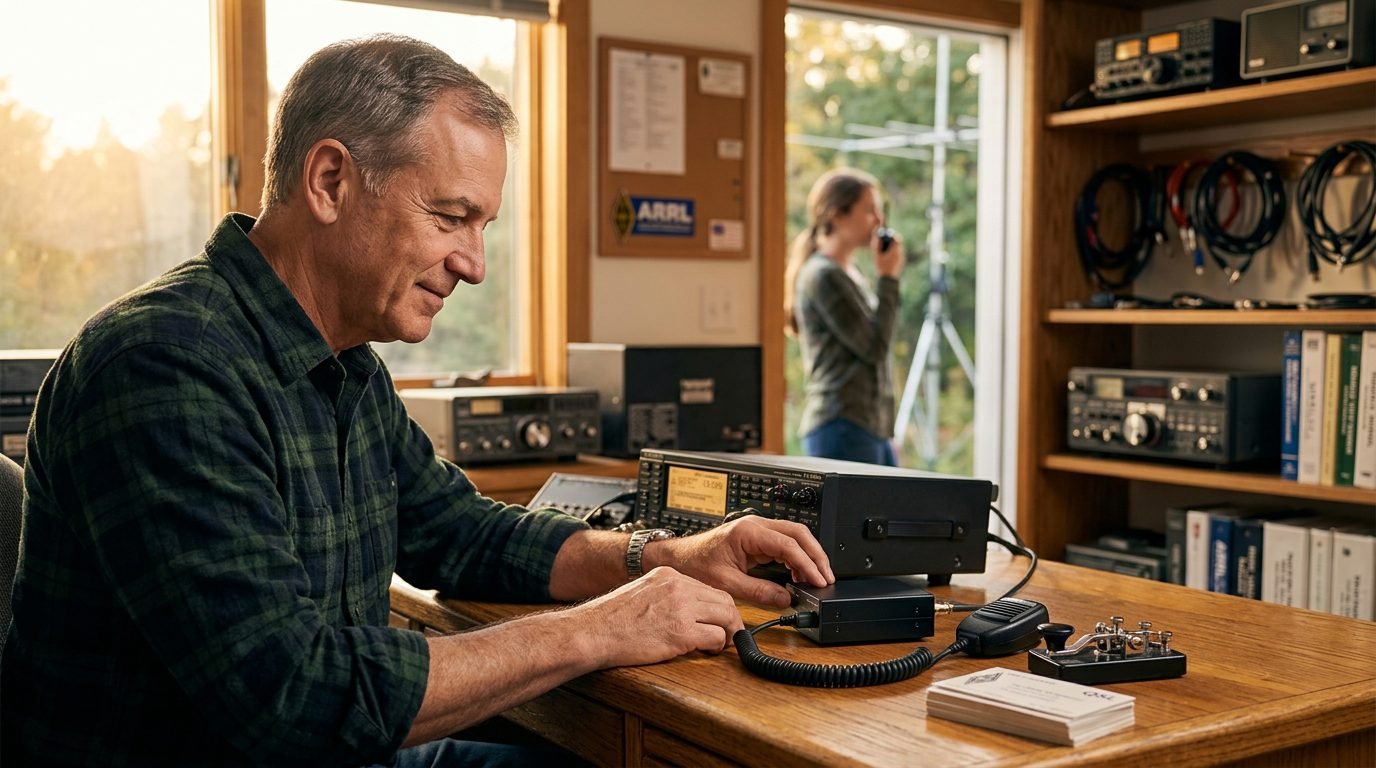
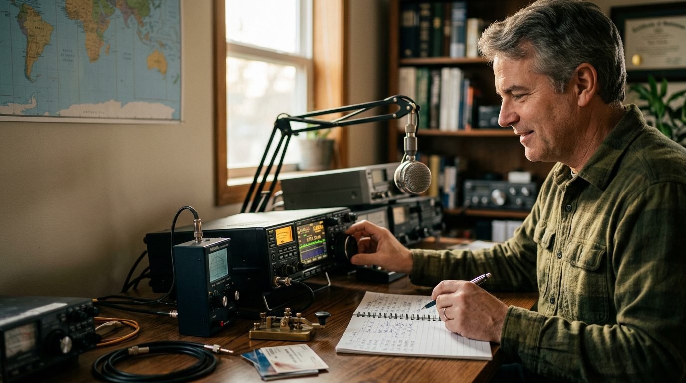 Portable and competitive operating continue to drive interest across the amateur-radio community.