Tag: amateur radio

  • Would a Beverage Antenna Improve My 160/80 Meter Reception?

    Would a Beverage Antenna Improve My 160/80 Meter Reception?

    I have been looking at one of the classic low-band receiving antennas: the Beverage antenna. The first thing to understand is that a Beverage is not about putting a stronger transmitted signal on the air. Its job is to help you hear weak stations better.

    For operators who spend time on 160 or 80 meters, especially when chasing DX through atmospheric noise and interference, that can be a very big deal.

    What Is a Beverage Antenna?

    A Beverage is a long, low wire receiving antenna, usually installed only a few feet above the ground and run in a fairly straight line. Traditional installations are often hundreds of feet long. It is normally used as a receive-only antenna.

    The reason people use one is not because it produces a huge signal on the S-meter. In fact, the received signal may be weaker than it is on a full-size transmitting antenna. What matters is the signal-to-noise ratio. A weak station that was buried in noise can become much easier to copy if the Beverage reduces noise arriving from other directions.

    Where a Beverage Really Shines

    The ARRL specifically discusses receiving wire antennas such as the Beverage for 160 and 80 meters, where large rotatable directional antennas are impractical for most hams. Those bands also tend to have high atmospheric noise, so improving receive directivity can be more useful than simply trying to collect a stronger signal.

    A Beverage can also be useful on 40 meters depending on its length, orientation and installation, but 160 and 80 meters are where the antenna has earned its reputation.

    The Important Word: Directional

    A properly installed Beverage favors signals arriving from a particular direction while reducing response to signals and noise from other directions. That makes orientation important. If I wanted to improve reception toward Europe, for example, I would plan the wire around that desired receiving direction rather than simply putting it wherever it happens to fit.

    There are also reversible and multi-direction Beverage systems for stations with enough property, but a single-wire Beverage is the simplest place to start.

    Would It Help With Local Electrical Noise?

    Possibly, but this needs a little nuance. A directional receiving antenna can do an excellent job when the unwanted noise is arriving predominantly from a direction that the antenna can reject. It is not a magic cure for every source of local radio-frequency interference. Noise generated very close to the station, feed line or antenna can still find its way into the receiver.

    That means a Beverage should be considered one part of a good low-noise receiving system, along with proper feed-line treatment, common-mode-current control and finding or reducing local noise sources whenever possible.

    My IC-7300MK2 Makes This Especially Interesting

    The Icom IC-7300MK2 has a feature that makes a separate receiving antenna particularly convenient: dedicated RX ANT IN/OUT SMA connectors. Icom specifically identifies these connections for receiving antennas, filters and preamplifiers.

    That means I can continue using my normal transmitting antenna while taking advantage of a Beverage for reception. I do not have to turn the Beverage into a transmitting antenna—and I should not try to transmit into a receive-only Beverage system.

    The Biggest Disadvantage: Space

    The Beverage antenna is electrically simple, but it wants real estate. W8JI’s extensive work with low-band receiving antennas points out the same basic tradeoff: the Beverage is simple and effective, but significant directivity requires substantial physical length.

    If you have the room for a long straight run of wire, that simplicity is part of its appeal. If your property cannot accommodate it, compact directional receiving antennas such as a K9AY, EWE, Flag or Pennant may deserve a look instead. For transmitting-antenna choices, I have also covered end-fed wires, verticals and hamsticks in a separate article.

    Quick Beverage Antenna Checklist

    • Best fit: weak-signal work on 160 and 80 meters.
    • Main benefit: improved signal-to-noise ratio and directional rejection.
    • Not a transmit upgrade: use it as a receive antenna.
    • Space required: expect a long, fairly straight wire run.
    • Installation matters: orientation, termination, grounding and feed-line isolation all affect performance.
    • Limited space? Consider a K9AY, EWE, Flag or Pennant receive antenna.

    So, Would I Benefit From One?

    For my station, the answer is yes—if I have enough space and I want to spend more time working weak signals on the lower HF bands.

    I would not install a Beverage expecting better transmit performance. I would install it because hearing is half of every QSO. If a distant station can hear me but I cannot pull that station out of the noise, more transmit power does not solve the receiving problem.

    For 160- and 80-meter DX, a good receive antenna can be one of the most worthwhile station improvements you can make.

    Bottom Line

    A Beverage antenna is a receiving tool, not a transmitting upgrade. If you have the room, operate the low bands and fight noise or weak-signal reception, it can give you something that another 100 watts cannot: a better chance of actually hearing the station calling you.


    References:
    ARRL — MF/HF Receiving Wire Antennas
    Icom America — IC-7300MK2
    W8JI — Beverage Antenna Construction

    73, NJ2RQ

  • From Mountain-Top Repeaters to Apps in Your Pocket: How Amateur Radio Learned to Link the World

    By NJ2RQ

    One of the most interesting stories in Amateur Radio is not simply how the radio itself evolved, but how hams learned to make one radio site talk to another. What began as a way to extend the range of a mobile or handheld signal became a worldwide web of repeaters, RF links, microwave paths, telephone interfaces, Internet gateways, digital reflectors, talkgroups, rooms, nodes and now smartphone applications.

    Today an operator can stand in a parking lot with a five-watt handheld, key a local repeater, enter a node number and come out through another station hundreds or thousands of miles away. Another operator can do nearly the same thing through D-STAR, DMR, Yaesu System Fusion, AllStarLink, a hotspot, or even an app running on a phone. To understand how we got here, it helps to start long before the Internet.

    The repeater idea came first

    Repeaters are much older than many operators realize. Experimental amateur relay stations existed on the old 5-meter band in the 1930s, and AM repeaters began appearing in the 1950s. The idea was simple: put a receiver and transmitter at a favorable location—often a hill, tower or tall building—so a weak mobile or handheld station could cover a much larger area.

    The real explosion came in the 1960s and 1970s with FM. Commercial land-mobile systems had already proven the value of channelized FM, and changing commercial channel requirements left large quantities of usable VHF and UHF equipment available as surplus. Hams converted that gear, developed duplexers and controllers, standardized repeater pairs and built networks on 2 meters, 70 centimeters and other bands. By the 1970s, the FM repeater had become one of the defining technologies of local Amateur Radio.

    A conventional repeater is still fundamentally local RF. You transmit on one frequency, the repeater receives you, and it retransmits your audio on another. Duplexers allow the receiver and transmitter to operate at the same site at the same time. A good location gives that modest handheld the coverage of a much larger station.

    Then repeaters started talking to repeaters

    Once clubs had reliable repeaters, the next question was obvious: why stop at one coverage area?

    Early linked systems used dedicated RF links, often on UHF or microwave frequencies, to carry audio and control signals between repeater sites. A city repeater could be tied to a mountaintop repeater, which could be tied to another site farther away. Statewide and regional systems became possible without asking every user to own a high-power station.

    Controllers became more sophisticated. DTMF touch tones could command links on and off. Autopatch systems let repeater users place telephone calls. Remote receivers, voting systems and microwave backbones improved coverage. In a sense, these systems were an early form of networking: RF sites were becoming nodes.

    The arrival of inexpensive Internet connectivity changed the architecture completely. Instead of leasing a telephone line or building a dedicated microwave path between every site, repeater audio could be digitized and transported as data. The Internet did not replace the repeater; it became another path between repeaters.

    IRLP and the beginning of Internet-era repeater linking

    One important bridge into the Internet era was the Internet Radio Linking Project, or IRLP, which began in the late 1990s. IRLP connected radio nodes through the Internet while preserving a radio-oriented operating style. It helped prove that reliable voice-over-IP could become part of everyday repeater operation.

    That concept opened the door for systems that were easier to access, more flexible and eventually usable from computers and smartphones as well as radios.

    EchoLink: the gateway that put the world behind a DTMF keypad

    EchoLink, developed by Jonathan Taylor, K1RFD, arrived in 2002 and became one of the most recognizable names in Amateur Radio VoIP.

    There is an important distinction here: EchoLink is best understood as a gateway system, not as a traditional RF link between two repeater sites. The Internet portion is carrying audio between authenticated EchoLink stations. A radio-connected EchoLink station provides the gateway between RF and that IP network. EchoLink identifies repeater gateways with an -R suffix and simplex RF links with an -L suffix.

    Every EchoLink station is assigned a unique node number. That number exists specifically so a radio user can control a gateway with DTMF tones. On a properly configured EchoLink repeater or simplex gateway, you can key your radio, send the DTMF digits for a desired node, and the EchoLink computer makes the Internet connection.

    Take WS2Q as an example. If WS2Q is operating as an EchoLink-accessible station or gateway, the live EchoLink directory identifies the station and its assigned node number. From an RF gateway that permits DTMF control, you can enter the node number and ask the gateway to connect. The exact control sequence can vary because sysops can customize DTMF commands, but the basic EchoLink model is simple: radio → local gateway → EchoLink network → distant node → radio.

    This was revolutionary because the user did not need to know IP addresses, server names or routing tables. A handheld and a numeric keypad could reach the world.

    D-STAR: digital voice designed for Amateur Radio

    D-STAR took a different path. The project grew from work by the Japan Amateur Radio League beginning in the late 1990s, with Icom helping turn the concept into working equipment. Unlike commercial systems later adopted by hams, D-STAR was conceived specifically around Amateur Radio digital voice and data.

    Its major advantage was that identity and routing were built into the system. Your callsign could travel with the digital transmission. Gateways could connect repeaters through the Internet. Reflectors allowed many repeaters and hotspots to meet in a common virtual space. Callsign routing made it possible to think in terms of reaching an operator rather than merely dialing a frequency.

    D-STAR also combined voice with low-speed data and location information, and the system included higher-speed data capability on 1.2 GHz. For hams accustomed to analog FM, it introduced a new idea: the repeater was no longer just retransmitting audio—it was participating in a digital network.

    DMR: commercial efficiency becomes an amateur worldwide network

    Digital Mobile Radio, or DMR, was first ratified as an ETSI standard in 2005. It was designed primarily for professional land-mobile radio, not Amateur Radio. That commercial origin is important because it explains both its strengths and its learning curve.

    DMR Tier II uses two-slot TDMA, allowing two logical conversations in one 12.5 kHz RF channel. Amateur operators adopted DMR radios and repeaters and then built enormous Internet-connected networks around them. Instead of simply linking repeater A to repeater B, DMR users select talkgroups. A talkgroup may be local, statewide, nationwide, worldwide or organized around a special interest.

    The result is extremely efficient and scalable. One repeater can participate in many different communities. The tradeoff is complexity: radio IDs, color codes, time slots, talkgroups and codeplugs can make a first DMR setup feel more like network administration than traditional FM.

    C4FM and Yaesu System Fusion: making digital migration easier

    Yaesu introduced System Fusion in 2013 using C4FM digital modulation. One of its most practical ideas was Automatic Mode Select. A compatible repeater could recognize analog FM or C4FM digital operation, helping clubs move toward digital without immediately abandoning every analog user.

    Through WIRES-X, System Fusion repeaters and nodes can connect over the Internet to rooms and other nodes around the world. For the operator, the experience is usually less dependent on manually building huge codeplugs than DMR. Digital voice, callsign information and data functions are integrated into the Yaesu ecosystem.

    System Fusion represents an important stage in repeater history: rather than replacing the analog repeater overnight, it offered a bridge where analog and digital users could coexist while the networking layer grew around them.

    NXDN: narrowband digital from Icom and Kenwood

    The correct name is NXDN. Icom and Kenwood began collaborating on the technology in 2003, announced it in 2005 and released the first conventional products in 2006. It was designed for narrowband land-mobile use and supports 6.25 and 12.5 kHz FDMA operation.

    Like DMR, NXDN came from the professional-radio world and later found an amateur following. Its narrow channel efficiency and strong commercial equipment heritage make it attractive, although its Amateur Radio footprint is smaller than DMR, D-STAR or System Fusion. It is another example of a recurring pattern in our hobby: professional communications technology becomes a new laboratory for amateur experimentation.

    AllStarLink: turn the repeater controller into an Internet PBX

    AllStarLink approached the problem from yet another direction. It is built around the open-source Asterisk telephone PBX and the app_rpt application. Instead of treating Internet linking as an accessory attached to a repeater, AllStar can become part of the repeater controller itself.

    An AllStar node may be a repeater, a remote base, a simplex node or a hotspot-style station. Nodes can connect to other nodes through VoIP, and DTMF commands provide control. The architecture is flexible enough to support large hubs, private networks and cross-links to other systems.

    AllStar is also known for very good audio when a system is configured well. Modern clients can use high-quality audio codecs, and because the network is carrying voice as IP data between nodes, the result can sound fuller and more natural than some heavily compressed digital-voice systems. That is not automatic—microphone level, RF deviation, codec choice, Internet quality and node configuration still matter—but a properly engineered AllStar path can sound excellent.

    PoC: when the “handy-talkie” starts using the cellular network

    Push-to-Talk over Cellular, usually abbreviated PoC, takes the familiar handheld-radio experience and moves the transport layer to LTE, 5G and Wi-Fi. The device may look and feel like an HT, complete with a side PTT button, loud speaker and rugged case, but the voice path is traveling through a cellular data network and a server rather than directly through an amateur repeater.

    The idea has roots in commercial push-to-talk cellular services such as Nextel and has matured into modern nationwide PTT systems. PoC devices can offer group calling, private calling, GPS, messaging and dispatch features over enormous geographic areas.

    For Amateur Radio, the interesting part is the user interface. Hams clearly like the immediacy of push-to-talk. PoC proves that the “radio experience” can exist even when RF is only at the cellular-network layer. That does not automatically make a PoC conversation Amateur Radio; the service, users and connection into amateur systems determine that. But the form factor is influencing how modern ham apps and network clients are being used.

    Zello: push-to-talk culture without a repeater

    Zello grew from an earlier product called LoudTalks and brought walkie-talkie-style voice to computers and smartphones. Press the button, talk, release and listen. That operating rhythm is instantly familiar to any radio operator.

    Zello itself is not an Amateur Radio repeater network. It is an Internet PTT platform. But it demonstrates why radio-style communication remains attractive even in a smartphone world. Groups can create channels, users can carry a Bluetooth PTT button, and the experience begins to resemble a networked HT.

    For hams, Zello is best viewed as a parallel development: it shows that the push-to-talk concept survived the transition from RF to apps and helped normalize the idea of carrying “radio-like” communications on a phone.

    RepeaterPhone: EchoLink and AllStarLink on Apple devices

    RepeaterPhone brings the concept back into the Amateur Radio networks themselves. It is an Apple-platform app for licensed operators that can connect to EchoLink and AllStarLink nodes. It provides a large PTT interface, directory searching, favorites, Bluetooth audio support and Apple Watch integration.

    As of this writing, RepeaterPhone is offered for the Apple ecosystem—iPhone, iPad and Apple Watch—not Android. For AllStarLink it supports high-quality audio codecs, which is one reason smartphone audio can be surprisingly good when the network path is configured properly.

    Think about how far that is from the 1970s repeater user. The old operator needed a radio, an RF path to the local machine and perhaps an autopatch. The modern operator can carry a network client in the same device used for maps, email and phone calls, yet still connect into repeater infrastructure built and maintained by hams.

    QSO One: the next step toward a universal amateur-radio network client

    QSO One is one of the newest developments in this story. Launched in 2026, it is designed as a modern client that brings multiple networks into one application. It currently supports Windows and Android, with additional platforms planned.

    The remarkable part is the scope: AllStarLink, EchoLink, IAX Direct, DMR, System Fusion and M17 are presented inside one software environment. That attacks one of the biggest problems created by decades of innovation—fragmentation. We gained many excellent digital systems, but each developed its own terminology, credentials, software and operating habits.

    If this model continues, the future operator may care less about which network is under the hood. The experience could become: choose the person, room, reflector, talkgroup or node you want, press PTT, and let the software handle the transport.

    So what is a repeater now?

    That question used to have an easy answer. A repeater was a receiver and transmitter on a tower.

    Now it may also be an RF endpoint in a worldwide network. It may route by callsign, node number, reflector, room or talkgroup. It may bridge analog FM into VoIP. It may accept traffic from a handheld, hotspot, computer or phone. A “node” may be a rack of equipment on a mountain—or an application running in somebody’s pocket.

    And yet the core idea has not changed at all.

    Amateur Radio has always been about extending communication beyond what one station could do alone. The relay operators of the earliest years did it manually. Repeaters automated it. RF links expanded it. The Internet globalized it. Digital voice organized it. Smartphones are now making it portable in a completely different way.

    Where the future is going

    The next phase will probably be less about inventing one more isolated network and more about connecting the networks we already have. Cross-mode gateways, software-defined radios, open protocols, better codecs, smarter routing and unified applications are already moving in that direction.

    There will always be operators who prefer a completely RF path, and there is real value in systems that continue working when commercial infrastructure fails. There will also be operators who enjoy worldwide linked systems, digital reflectors and smartphone clients. Those are not mutually exclusive versions of Amateur Radio. They are different layers of the same century-long experiment.

    From a converted commercial FM radio on a mountaintop to EchoLink node numbers, D-STAR callsign routing, DMR talkgroups, C4FM rooms, NXDN narrowband channels, AllStar nodes, PoC handhelds, Zello, RepeaterPhone and QSO One, the pattern is remarkably consistent:

    Hams find a new communications technology, take it apart, connect it to something else, and ask one question: “How far can we make this go?”

    Sources and further reading
  • How to Work DX Split Without Becoming That Guy

    How to Work DX Split Without Becoming That Guy

    Working a rare DX station in a pileup is one of the most satisfying parts of HF operating. It is also one of the easiest places to create unnecessary interference if your split setup is wrong.

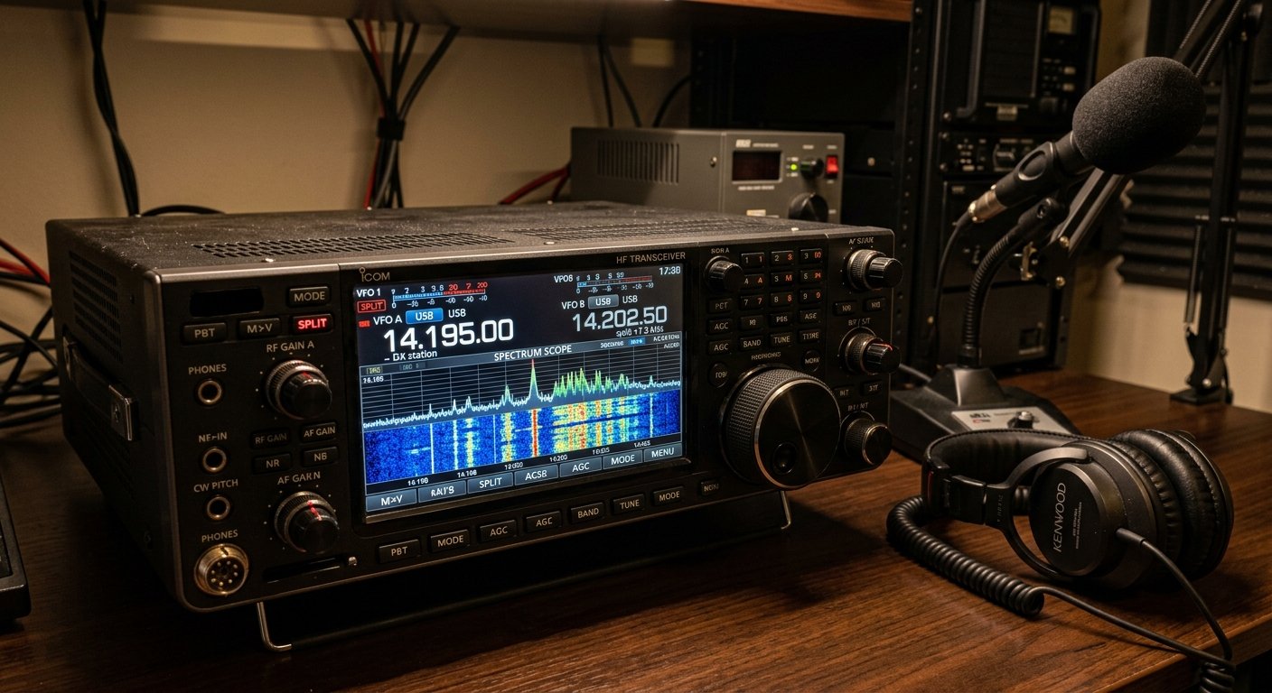
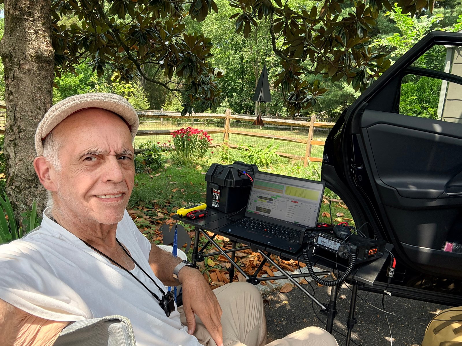
    HF transceiver configured for split-frequency DX operation
    Split operation keeps you listening to the DX station while transmitting where the DX operator is actually listening.

    The good news is that split operation is not complicated once you understand what the DX station is doing: you listen on one frequency and transmit on another.

    What “up 5” actually means

    Suppose a DX station is transmitting on 14.195 MHz and says, “up 5.” You keep listening to the DX on 14.195, but your transmitter goes roughly 5 kHz higher, around 14.200 MHz. If the operator says “up 5 to 10,” they are listening across a range rather than on one exact frequency.

    That is the whole purpose of split: keep dozens or hundreds of callers from transmitting directly on top of the DX station’s signal.

    Listen before you touch PTT

    The first job is not calling. It is listening.

    Before transmitting, figure out:

    • the DX station’s correct call sign,
    • whether the operator is working simplex or split,
    • whether they said up, down, or gave a range,
    • whether they are calling for a specific region or call-sign number, and
    • where the stations being answered are actually transmitting.

    ARRL’s DX guidance emphasizes that you should not call a station you cannot hear and that once the DX operator acknowledges another caller, everyone else should stop transmitting until that contact is finished.

    Set up the two VFOs carefully

    On a typical modern HF transceiver, VFO A can stay on the DX station while VFO B is set to your transmit frequency. After enabling SPLIT, confirm which VFO will transmit before you call.

    This is where mistakes happen. If the VFOs are reversed, you may transmit directly on the DX frequency and cover up the very station everyone is trying to hear.

    Use the radio’s display, split indicator, TX-frequency preview, or VFO swap function to verify your transmit frequency without blindly keying the microphone.

    Your transmit frequency still has to be legal

    A DX station can listen anywhere that is legal for that station, but you must transmit only where your license and operating rules allow. For U.S. operators, that means checking your authorized band and mode segment before transmitting. A split instruction does not override your license privileges.

    This becomes especially important when working international stations whose band allocations differ from ours.

    Find the operator’s pattern

    Calling exactly “up 5” every time is not always the best approach. A skilled DX operator may tune slowly through a listening range or jump around within it.

    Listen to the stations the DX is actually working. If you can hear or see where the successful callers are transmitting, you can often identify the operator’s pattern and place your next call intelligently instead of transmitting blindly.

    A panadapter or second receiver can make this easier, but careful listening works too.

    Call once, then listen

    Send your full call sign clearly, then listen. Repeating your call continuously only adds to the pileup and can make it harder for the DX operator to pull out anyone’s call.

    If the DX operator comes back with a partial call that is not yours, stay quiet. If they ask for a particular number or geographic area that does not include you, stay quiet. Your turn will come faster when everyone follows the operator’s instructions.

    Do not become the pileup police

    Someone will eventually transmit on the wrong frequency. It happens. Resist the temptation to key up and correct them.

    Sending “UP!” over and over usually creates even more interference. ARRL has specifically advised operators not to become pileup policemen. Let the DX operator manage the pileup and concentrate on your own operating.

    A simple split checklist

    • Hear and identify the DX station first.
    • Determine exactly where the DX is listening.
    • Set RX and TX VFOs correctly.
    • Confirm your transmit frequency is legal for your license and mode.
    • Listen for the DX operator’s rhythm and pattern.
    • Send your full call once, then listen.
    • Stop calling when another station is being worked.
    • Never transmit on the DX frequency unless the operator is working simplex.

    The real advantage is discipline

    Breaking a pileup is not just about having the biggest amplifier or antenna. Knowing your radio, listening carefully, understanding the operator’s pattern, and transmitting at the right moment can make a major difference.

    Set split correctly, stay inside your privileges, and make your call count. That gives you a better chance of putting the DX in the log without becoming part of the interference.

    Roger Quintana, NJ2RQ — LuffyHamVault.com

    Further reading

    ARRL has useful guidance in Chasing DX and its article Advice to Avoid DXpedition Confusion. U.S. operators should also check the current ARRL Band Plan and FCC operating privileges before transmitting.

  • Common-Mode Current Explained: Why Ferrite Chokes Matter

    Common-Mode Current Explained: Why Ferrite Chokes Matter

    Common-mode current is one of those amateur-radio problems that can hide in plain sight. Your SWR may look reasonable, the radio may transmit normally, and yet the coax can still be carrying RF where you do not want it.

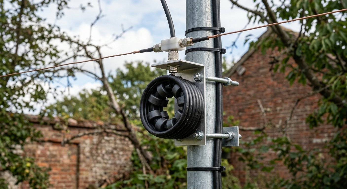
    Ferrite common-mode choke installed on an amateur radio coaxial feed line
    A ferrite common-mode choke on an HF coax feed line. Its job is to impede unwanted RF current on the outside of the shield.

    In a properly behaving coaxial feed line, the wanted RF currents flow on the center conductor and the inside surface of the shield. Those currents are equal and opposite, so fields outside the cable largely cancel. Common-mode current is different: it flows on the outside surface of the coax shield. Once that happens, part of the feed line can begin acting like another piece of the antenna.

    Why common-mode current matters

    If the outside of the coax becomes part of the radiating system, several things can happen. RF can travel back toward the operating position, antenna tuning can become less predictable, the radiation pattern can change, and nearby electronics may be more likely to experience interference. On receive, the same feed line can also pick up noise from devices in and around the house and carry it toward the antenna system.

    That does not mean every noise problem is caused by common-mode current, and a choke is not a universal cure. But when the outside of the feed line is carrying unwanted RF, a properly designed common-mode choke is one of the standard tools used to reduce it.

    What a ferrite choke actually does

    A common-mode choke adds impedance to RF current trying to flow along the outside of the coax shield. Ferrite material is especially useful because it can provide substantial impedance over a useful range of HF frequencies without interrupting the normal signal path inside the coax.

    The goal is not to “block the coax” or change its 50-ohm characteristic impedance. The wanted differential-mode signal still travels through the cable. The choke is aimed at the unwanted common-mode path on the outside of the shield.

    Ferrite type, the number of beads or turns, frequency, cable size, and power level all matter. This is why a random clip-on ferrite of unknown composition may work well at one frequency and do very little at another. ARRL guidance has long emphasized using ferrite material with known characteristics, while modern commercial HF feed-line chokes are commonly designed around materials such as Mix 31 for broad HF coverage.

    Where should the choke go?

    For antenna-system common-mode problems, the feed point is often the first place to consider. A choke there can help keep the outside of the coax from becoming part of the antenna. Depending on the installation, another choke near the station entrance can also be useful for reducing RF that might otherwise reach equipment in the shack.

    Placement is not one-size-fits-all. End-fed antennas, verticals, dipoles, and multiband systems can each create different current distributions. A choke can improve isolation, but it does not replace a sound antenna design, a suitable counterpoise or radial system where required, good bonding, and proper lightning protection.

    My station example

    At my own station I use purpose-built MyAntennas common-mode chokes, including a CMC-154S-3K at the coax entry. That is a different job from an antenna tuner. The tuner transforms impedance so the transmitter sees a suitable load; the common-mode choke is there to discourage unwanted RF current from traveling on the outside of the feed line.

    That distinction matters. A 1:1 SWR reading at the radio does not prove that common-mode current is absent, just as adding a choke does not automatically make a poorly designed antenna efficient.

    Signs that are worth investigating

    Common-mode current becomes especially worth checking when touching the radio, microphone, coax, or another cable changes the behavior of the station; when transmitted RF gets into audio, USB, computer, or control equipment; when antenna tuning changes as the feed line is moved; or when a feed line appears to be influencing the antenna pattern. Those symptoms can have other causes, but they are good reasons to examine feed-line isolation.

    The practical takeaway

    Think of a ferrite common-mode choke as an RF isolator for the outside of the feed line. It does not tune the antenna, and it does not replace good grounding, bonding, or antenna design. What it can do is keep the coax from participating in the antenna system in ways you did not intend.

    For many HF installations, that can mean more predictable tuning, less RF in the shack, and a cleaner boundary between the antenna and the station.

    Roger Quintana, NJ2RQ — LuffyHamVault.com

    Further reading

    For more technical background, see the ARRL Interference Primer and DX Engineering’s information on baluns, ununs and RF chokes.

  • What an Antenna Tuner Really Does — and What It Doesn’t Do

    What an Antenna Tuner Really Does — and What It Doesn’t Do

    If you have ever pressed TUNE, watched the SWR drop, and thought the antenna itself was suddenly “fixed,” you are not alone. An antenna tuner is one of the most useful pieces of HF gear in a station — but its name is a little misleading.

    The tuner does not usually change the physical antenna. Instead, it changes the impedance the radio sees so the transmitter can work into a load that is close to the 50 ohms most modern transceivers expect.

    What the tuner actually does

    An antenna system includes the antenna, feed line, connectors, and anything else between the transmitter and the radiating element. If that system does not present roughly 50 ohms at the radio, the transmitter sees a mismatch and the SWR rises.

    A tuner uses combinations of inductance and capacitance to transform that impedance. From the radio’s side of the tuner, the load can now look close to 50 ohms, allowing the transmitter to deliver power normally instead of reducing output to protect its final amplifier.

    That is the real job: impedance matching.

    What it does not do

    A station tuner does not magically remove the mismatch that exists farther down the line. If the antenna and feed line create a high SWR on the antenna side of the tuner, that standing-wave condition is still there after the tuner finds a match.

    This is why a beautiful 1:1 reading at the radio does not automatically mean the entire antenna system is efficient. The tuner can make the transmitter happy while loss is still occurring in the coax.

    Why feed-line loss matters

    All feed lines have loss, even when perfectly matched. With coax, a high SWR adds additional loss because RF energy makes repeated trips through a lossy transmission line before it is ultimately radiated or dissipated. The effect becomes more important with longer coax runs, higher frequencies, and higher SWR.

    High SWR can also create higher RF voltage or current at points along the system. That can stress coax, connectors, tuner components, and other hardware if the mismatch and power level are severe enough.

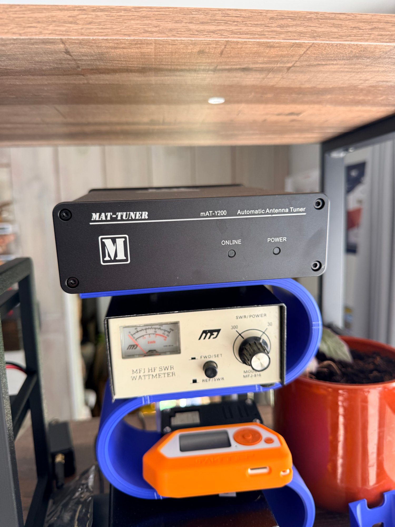
    MAT-Y200 automatic antenna tuner in an amateur radio station
    A real MAT-Y200 automatic antenna tuner from my station. The tuner provides an impedance match for the transmitter; it does not physically retune the antenna.

    Where the tuner sits makes a difference

    A tuner located in the shack protects the radio and gives it a good match, but the coax between the tuner and antenna can still be operating at high SWR. A remote tuner mounted at or near the antenna feed point can transform the impedance before the signal travels through the coax. That can substantially reduce mismatch-related coax loss in systems where the untuned feed-point impedance is far from 50 ohms.

    This is one reason remote automatic tuners are popular with non-resonant wires and some portable or multiband installations.

    A practical portable example

    Suppose you set up a portable vertical on 40 meters and the analyzer shows 3.5:1 SWR. A tuner at the radio may easily make the transceiver see 1.2:1. You can transmit, and the radio is satisfied — but the coax between the tuner and the antenna still has the original mismatch.

    If instead you adjust the whip, coil, or radial system until the antenna itself is near resonance and presents a reasonable match, the feed line operates under easier conditions. The tuner may then need to make only a small correction, or no correction at all.

    The best way to think about a tuner

    Think of an antenna tuner as a matching network, not an antenna repair device. It is extremely useful when an otherwise workable antenna presents an impedance your radio does not like. It can broaden the usable range of an antenna system and make multiband operation much more convenient.

    But it cannot turn a poor radiator into a great one, recover power already lost as heat in the feed line, or replace good antenna design. Whenever possible, start with an efficient antenna, good feed line, solid connections, and a sensible installation. Then let the tuner do the job it was designed to do: provide the radio with the impedance match it needs.

    Roger Quintana, NJ2RQ — LuffyHamVault.com

    Further reading

    For deeper reading, see ARRL’s “More About Antenna Tuners” and “Feed Lines”, which explain the same distinction between matching the transmitter and changing the actual SWR on the antenna side of the tuner.

  • How to Start in Amateur Radio: A Beginner’s Guide

    How to Start in Amateur Radio: A Beginner’s Guide

    Introduction to Amateur Radio

    If you’re looking for an exciting hobby that connects you with people from all around the world, amateur radio is a fantastic choice. Whether you want to talk to friends or explore the world of radio technology, this guide will help you start your journey in easy steps.

    Step 1: Understand the Basics

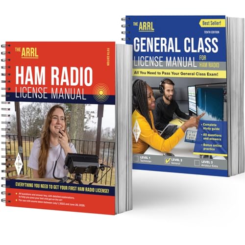
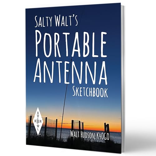
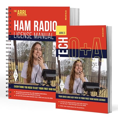
    To get started, familiarize yourself with the fundamental concepts of amateur radio. This includes learning about the different frequency bands, available equipment types, and licensing requirements in your country. Understanding these basics is key to ensuring a smooth transition into the amateur radio community. Here are some great books that can assist you in the licensing process.

    Step 2: What is Required, Licensing

    Getting licensed as an amateur radio operator is a straightforward process that begins with the Technician Class license, the entry-level gateway to the hobby. To earn it, you must pass a 35-question multiple-choice exam covering basic radio theory, regulations, and safety. Once you pass, you’ll register with the FCC to receive your official call sign. There is no longer a Morse code requirement for any U.S. license, making it more accessible than ever for new hobbyists to start transmitting on VHF and UHF bands.

    Helpful Resources & Links

    • ARRL (American Radio Relay League): As the national association for amateur radio, the ARRL is the best place to start. They offer a Step-by-Step Licensing Guide and an Exam Session Search to find a test location near you (often hosted by local clubs).
    • FCC Guidelines: The FCC regulates the service under Part 97 rules. You must obtain an FCC Registration Number (FRN) through the CORES system before taking your exam. Note that the FCC charges a $35 application fee for new licenses, payable after you pass your exam.
    • Study Tools: * ARRL Exam Review: Free online practice tests.
      • HamStudy.org: A popular, free tool for tracking your progress through the question pools.

    Quick Reference Table

    License ClassExam LengthBest For
    Technician35 QuestionsLocal communication, handheld radios, and emergency prep.
    General35 QuestionsWorldwide “DX” communication on High Frequency (HF) bands.
    Amateur Extra50 QuestionsFull access to all U.S. amateur frequencies and modes.

    Stay tuned for my personal experience, which radios I started with, and where I am in the journey at present. I will share my interests, successes, and failures (we learn from them).

    For now, wherever in the journey you may be, please share your experiences in the Facebook Group FOTA, Freemasons on the Air. https://www.facebook.com/groups/980766738227414